Unit: AM/FM Stereo Receiver
Manufacturer: Allied
Model: 435
SN: QG 16205
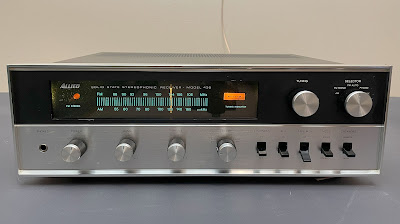
Today I am featuring a vintage Allied Model 435 receiver that came in for restoration. The information available online about this model could be more extensive. I was only able to find basic information. Apparently, this receiver was introduced in 1973. Output power is only 7.5 W per channel into 8 ohms. The retail price in 1973 was $179.95 (Ref. Radio Shack, 50th Anniversary Electronics Catalog 1973, page 97).
Note. The scanning quality of the instruction manual available online for this model is very poor. I have tried to identify each electronic component as accurately as possible, but some errors may still exist.
Power Supply Board (W16-030)
The power supply board has 3 aluminum electrolytic capacitors: C1, C2, and C3. All of them were replaced with low-impedance Nichicon UPW caps.
The original e-caps were tested with an Atlas ESR70 capacitance meter; the results are below. Almost all electrolytic capacitors on all boards deviated by more than 20% from the nominal capacitance.
Test results on original capacitors removed from the power supply board:
C1: rated capacitance – 100uF, measured – 123uF, ESR – 0.48Ω, deviation: +23%
C2: rated capacitance – 10uF, measured – 16uF, ESR – 5.8Ω, deviation: +60%
C3: rated capacitance – 100uF, measured – 124uF, ESR – 0.59Ω, deviation: +24%
I also replaced both NPN transistors on this board to improve the reliability of the power supply. Below is a list of original and replacement transistors that I have used.
Q1: NPN, 2SC968 (original), replaced with a new Fairchild KSC2383YBU
Q2: NPN, 2SC971 (original), replaced with a new Fairchild KSC2690AYSTU
Power supply board - before and after
Audio Unit (W15-043)
The audio unit has 21 aluminum electrolytic capacitors (C301, C302, C307, C308, C311, C312, C313, C314, C315, C316, C317, C318, C327, C328, C331, C332, C341, C342, C345, C346, C347) and two bi-polar e-caps (C329, C330).
All ordinary aluminum e-caps installed in the signal path, except for C313 and C314, were replaced with low-leakage Nichicon UKL capacitors to reduce the noise generated in the circuit. The original capacitors C313 and C314 were replaced with high-quality film polyester WIMA caps. Two original bi-polar capacitors were replaced with new bi-polar Nichicon UES caps. The remaining aluminum e-caps were replaced with low-impedance Nichicon UPW caps.
Test results on original capacitors removed from the audio unit:
C301: rated capacitance – 3.3uF, measured – 4.2uF, ESR – 2.7Ω, deviation: +27%
C302: rated capacitance – 3.3uF, measured – 4.5uF, ESR – 3.2Ω, deviation: +36%
C307: rated capacitance – 10uF, measured – 15uF, ESR – 2.8Ω, deviation: +50%
C308: rated capacitance – 10uF, measured – 13uF, ESR – 2.6Ω, deviation: +30%
C311: rated capacitance – 220uF, measured – 329uF, ESR – 0.24Ω, deviation: +50%
C312: rated capacitance – 220uF, measured – 286uF, ESR – 0.26Ω, deviation: +30%
C313: rated capacitance – 1uF, measured – 1.8uF, ESR – 3.1Ω, deviation: +80%
C314: rated capacitance – 1uF, measured – 1.6uF, ESR – 2.7Ω, deviation: +60%
C315: rated capacitance – 3.3uF, measured – 3.9uF, ESR – 2.8Ω, deviation: +18%
C316: rated capacitance – 3.3uF, measured – 4.5uF, ESR – 3.4Ω, deviation: +36%
C317: rated capacitance – 47uF, measured – 64uF, ESR – 1.22Ω, deviation: +36%
C318: rated capacitance – 47uF, measured – 66uF, ESR – 1.16Ω, deviation: +40%
C327: rated capacitance – 3.3uF, measured – 4.6uF, ESR – 3.2Ω, deviation: +39%
C328: rated capacitance – 3.3uF, measured – 4.3uF, ESR – 3.5Ω, deviation: +30%
C329: rated capacitance – 33uF, measured – 34uF, ESR – 1.02Ω, deviation: +3%
C330: rated capacitance – 33uF, measured – 33uF, ESR – 0.91Ω, deviation: 0%
C331: rated capacitance – 47uF, measured – 61uF, ESR – 0.66Ω, deviation: +30%
C332: rated capacitance – 47uF, measured – 69uF, ESR – 0.59Ω, deviation: +47%
C341: rated capacitance – 47uF, measured – 64uF, ESR – 1.14Ω, deviation: +36%
C342: rated capacitance – 47uF, measured – 60uF, ESR – 1.59Ω, deviation: +28%
C345: rated capacitance – 47uF, measured – 64uF, ESR – 1.24Ω, deviation: +36%
C346: rated capacitance – 47uF, measured – 61uF, ESR – 1.25Ω, deviation: +30%
C347: rated capacitance – 220uF, measured – 324uF, ESR – 0.32Ω, deviation: +47%
This board has two 2SC871 transistors installed in positions Q301/Q302 and six 2SC870 transistors installed in positions Q303 through Q308. Both are on my list of transistors prone to failure. I replaced them with a modern low-noise Fairchild KSC1845. Watch pinout when replacing transistors. The original 2SC870/2SC871 transistor is BCE, and the new one (KSC1845) is ECB.
Audio unit - before and after
The tuner board has 11 aluminum electrolytic capacitors: C35, C41, C62, C66, C72, C73, C78, C79, C82, C88, and C89.
All original e-caps with a nominal capacitance of 1uF or less were replaced with film polyester WIMA caps. The remaining aluminum e-caps were replaced with low-impedance Nichicon UPW caps.
Test results on original capacitors removed from the tuner unit:
C35: rated capacitance – 0.47uF, measured – 0.58uF, ESR – N/A, deviation: +23%
C41: rated capacitance – 4.7uF, measured – 7.1uF, ESR – 2.1Ω, deviation: +51%
C62: rated capacitance – 4.7uF, measured – 7.2uF, ESR – 2.4Ω, deviation: +53%
C66: rated capacitance – 1uF, measured – 1.5uF, ESR – 2.7Ω, deviation: +50%
C72: rated capacitance – 0.47uF, measured – 0.82uF, ESR – N/A, deviation: +75%
C73: rated capacitance – 100uF, measured – 145uF, ESR – 0.52Ω, deviation: +45%
C78: rated capacitance – 100uF, measured – 152uF, ESR – 0.41Ω, deviation: +52%
C79: rated capacitance – 33uF, measured – 56uF, ESR – 0.49Ω, deviation: +70%
C82: rated capacitance – 0.47uF, measured – 0.88uF, ESR – N/A, deviation: +87%
C88: rated capacitance – 0.47uF, measured – 0.81uF, ESR – N/A, deviation: +72%
C89: rated capacitance – 0.47uF, measured – 0.83uF, ESR – N/A, deviation: +77%
This board also has 5 prone-to-failure transistors (2SC711 and 2SC710) installed in positions Q8 through Q12. I replaced them with a low-noise Fairchild KSC1845 transistor. Watch pinout when replacing transistors. The original 2SC710/2SC711 transistor is BCE, and the new one (KSC1845) is ECB.
Tuner unit - before and after
Main Filter and Two Coupling Capacitors
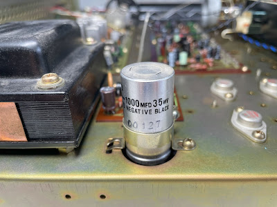
The original filter capacitor C3 was replaced with a new Nichicon LKG capacitor. The new capacitor is slightly larger in diameter compared to the original (25 mm versus 22 mm). To compensate for this difference, I installed a new Kemet clamp.
The original axial coupling capacitors C9 and C10 installed in the output signal path were replaced with new Vishay axial e-caps (138 AML series).
Test results on the original filter and coupling capacitors:
C3: rated capacitance – 1000uF, measured – 1520uF, ESR – 0.27Ω, deviation: +52%
C9: rated capacitance – 1000uF, measured – 1484uF, ESR – 0.18Ω, deviation: +48%
C10: rated capacitance – 1000uF, measured – 1668uF, ESR – 0.24Ω, deviation: +67%
Original and new main filter capacitor
New axial coupling capacitors (sorry, I forgot to take a picture of the original coupling caps)
Dial, Dial Pointer, Meter, and Stereo Indicator Lamps
Replacing the dial lamps on this receiver is a simple task. Just remove the front panel and pull out the lamps from their sockets. I replaced the old incandescent bulbs with warm white LED lamps to maintain the original look and decrease heat.
Dial lamps - before and after
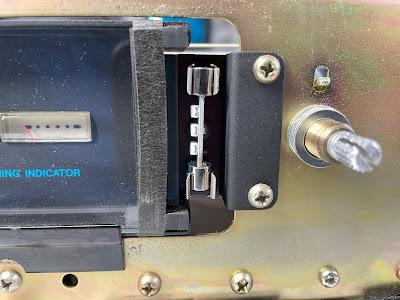
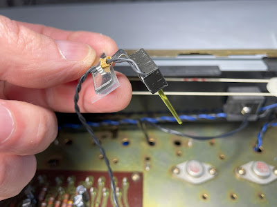
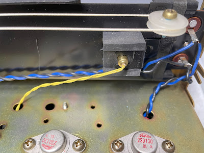
Replacing the dial pointer lamp in almost any vintage receiver is the most tedious job. This is very delicate work and there is always a chance of breaking the tiny and fragile pointer. So, pay extra attention while replacing this lamp. The original dial pointer lamp burned out in this unit and I replaced it with a new 4.7mm incandescent lamp.
Dial pointer lamp - before and after
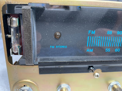
The rubber socket for the stereo indicator lamp is still in great shape and I replaced the old bulb with a new 4.7mm incandescent lamp.
Stereo indicator lamp - before and after
Output Power Test
The final output power test was performed at the end of my restoration. The receiver was loaded with a low inductance 8Ω/100W dummy resistor for each channel. The oscilloscope was connected across the speaker terminals and a sine-wave signal of 1kHz was applied to the AUX jacks. The output sine-wave signal was perfectly symmetrical on both channels with no clipping up to 7.25 VRMS (left channel) and 7.35 VRMS (right channel). It corresponds to the output power of 6.6W on the left channel and 6.8W on the right channel.
Output power test
As usual, all the knobs and the front panel were gently cleaned in warm water with dish soap. All controls have been cleaned with DeoxIT 5% contact cleaner and lubricated with DeoxIT FaderLube 5% spray.
The final result can be seen in the photos below. This receiver sounds very good! Please watch a short demo video at the end of this post. Thank you for reading.
Allied Model 435 - after restoration

_before%20servicing.jpg)
_after%20servicing.jpg)
_before%20servicing.jpg)
_after%20servicing.jpg)
_before%20servicing.jpg)
_after%20servicing.jpg)






No comments:
Post a Comment