Unit: Stereo Integrated Amplifier
Manufacturer: McIntosh
Model: MA 6100
SN: AE8043
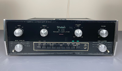
Today I'm showing a magnificent McIntosh MA 6100 integrated amplifier that came in for restoration.
The MA 6100 is a solid-state, direct-coupled amplifier that was manufactured from 1972 to 1979. It produces 70 watts per channel into 8 ohms with no more than 0.2% total harmonic distortion. The damping factor at 8 ohms is 50. The retail price in 1975 was $699.00. An interesting review of this model was published in Modern Recording, Vol. 1 No. 3, page 50, 1976.
Left and Right Channel PreAmp Board (044-512)
Each preamp board has one ROE electrolytic capacitor (C107/C108) and 3 ordinary aluminum electrolytic capacitors: C105/C106, C113/C114, C123/C124.
The original ROE e-caps (EK Series with Bakelite Case and encapsulant) were replaced with modern low-leakage Nichicon UKL caps. The remaining aluminum e-caps were replaced with low-impedance Nichicon UPW caps.
All original e-caps were tested with an Atlas ESR70 capacitance meter; the results are below.
Please note that the 4 original capacitors installed on these two boards drifted from the nominal capacitance by more than 40%. The measured capacitance of original ROE e-caps C107 and C108 is almost double their rated capacitance!
Test results on original capacitors removed from the left and right channel PreAmp boards:
C105: rated capacitance – 10uF, measured – 11uF, ESR – 1.93Ω, deviation: +10%
C106: rated capacitance – 10uF, measured – 11uF, ESR – 2.11Ω, deviation: +10%
C107: rated capacitance – 10uF, measured – 18uF, ESR – 0.75Ω, deviation: +80%
C108: rated capacitance – 10uF, measured – 20uF, ESR – 0.98Ω, deviation: +100%
C113: rated capacitance – 100uF, measured – 119uF, ESR – 0.44Ω, deviation: +19%
C114: rated capacitance – 100uF, measured – 146uF, ESR – 1.31Ω, deviation: +46%
C123: rated capacitance – 100uF, measured – 108uF, ESR – 0.42Ω, deviation: +8%
C124: rated capacitance – 100uF, measured – 141uF, ESR – 0.63Ω, deviation: +41%
Two original carbon resistors with 5% tolerance (R115, R116) were replaced with 1% tolerance KOA Speer metal film resistors. The other two carbon resistors with 5% tolerance (R117, R118) were replaced with 1% tolerance Yageo metal film resistors.
I also decided to unsolder and test each pair of original BC109C transistors installed in the differential amplifier (Q107/Q109 and Q108/Q110) to assess their matching. Each pair of transistors is supposed to be precisely matched to work properly in the circuit. Below are the testing results for the original BC109C transistors from each channel.
Test results on original BC109C transistors
Q107 (left channel): hfe - 545, Vbe - 0.737V
Q109 (left channel): hfe - 476, Vbe - 0.754V
Q108 (right channel): hfe - 549, Vbe - 0.765V
Q110 (right channel): hfe - 548, Vbe - 0.762V
The mismatch between the two transistors in the left channel is approximately 14%. This level of mismatch is quite high and can result in a high DC offset. In contrast, in the right channel, the mismatch between the two transistors is almost 0%.
I decided to replace all the OEM transistors with the new Central Semiconductor BC109C to ensure the differential amplifier circuit was working properly. Before installation, each pair of BC109C transistors was meticulously matched for current gain and base-emitter voltage.
Test results on new closely matched BC109C transistors
Q107 (left channel): hfe - 619, Vbe - 0.767V
Q109 (left channel): hfe - 618, Vbe - 0.769V
Q108 (right channel): hfe - 617, Vbe - 0.768V
Q110 (right channel): hfe - 618, Vbe - 0.769V
The original BC109C transistors installed in positions Q111 and Q112 were also replaced with new Central Semiconductor BC109C transistors.
Left channel PreAmp board - before and after
Right channel PreAmp board - before and after
Left and Right Channel Power Output Boards (044-585)
Each power output board has one solid tantalum capacitor (C427/C428) installed in the input signal path, one axial filtering e-cap (C401/C402), one ROE bi-polar e-cap (C419/C420) installed in the crowbar circuit, and one radial aluminum electrolytic capacitor (C403/C404).
The original tantalum capacitors were replaced with high-quality film polyester WIMA caps. The original axial capacitors were replaced with new axial Vishay caps. The original bi-polar ROE e-caps (EKU Series with Bakelite Case and encapsulant) were replaced with new bi-polar Nichicon UES caps. The remaining aluminum e-caps were replaced with low-impedance Nichicon UPW caps.
Test results on original capacitors removed from the left and right channel power output boards:
C401: rated capacitance – 150uF, measured – 161uF, ESR – 0.38Ω, deviation: +7%
C402: rated capacitance – 150uF, measured – 152uF, ESR – 0.26Ω, deviation: +1%
C403: rated capacitance – 100uF, measured – 123uF, ESR – 0.68Ω, deviation: +23%
C404: rated capacitance – 100uF, measured – 122uF, ESR – 1.43Ω, deviation: +22%
C419: rated capacitance – 10uF, measured – 12uF, ESR – 0.66Ω, deviation: +20%
C420: rated capacitance – 10uF, measured – 13uF, ESR – 0.68Ω, deviation: +30%
C427: rated capacitance – 1.5uF, measured – 1.6uF, ESR – 9.2Ω, deviation: +7%
C428: rated capacitance – 1.5uF, measured – 1.7uF, ESR – 8.8Ω, deviation: +13%
All original carbon resistors with 5% tolerance (R405, R406, R411, R412, R421, R422, R423, R424) were replaced with 1% tolerance KOA Speer metal film resistors.
Left channel power output board - before and after
Right channel power output board - before and after
Reg & Phase Inverter Board (044-419)
This board has one radial aluminum electrolytic capacitor C302, and 2 axial e-caps (C303, C307).
This board was previously serviced and a low-quality Jamicon e-cap was installed in position C302. The service manual calls for this position a solid tantalum capacitor. I replaced it with a modern low-leakage Nichicon UKL cap. The original axial capacitors were with new axial Vishay caps.
Test results on original capacitors removed from the reg & phase inverter board:
C302: rated capacitance – 10uF, measured – 11uF, ESR – 1.04Ω, deviation: +10%
C303: rated capacitance – 33uF, measured – 41uF, ESR – 0.32Ω, deviation: +24%
C307: rated capacitance – 100uF, measured – 132uF, ESR – 0.77Ω, deviation: +32%
Reg & phase inverter board - before and after
Power Supply Section (154-616)
The power supply section has one triple electrolytic capacitor C312 (sections A, B, and C), 2 main filter capacitors (C313, C314), and one axial e-cap C317.
The original triple e-cap C312 (sections B and C) and two main filter caps (C313, C314) were tested in-circuit with Atlas ESR70 capacitance meter. These capacitors are still within the factory capacitance tolerance and have very low ESR.
In-circuit test on triple e-cap C312 and two main filter capacitors C313 & C314
C312B: rated capacitance – 150uF, measured – 178uF, ESR – 0.81Ω, deviation: +19%
C312C: rated capacitance – 150uF, measured – 176uF, ESR – 0.64Ω, deviation: +17%
C313: rated capacitance – 9300uF, measured – 10360uF, ESR – 0.12Ω, deviation: +11%
C314: rated capacitance – 9300uF, measured – 10440uF, ESR – 0.11Ω, deviation: +12%
The original axial e-cap C317 was replaced with a new axial Vishay capacitor.
Test result on original capacitor removed from the power supply section:
C317: rated capacitance – 220uF, measured – 237uF, ESR – 0.16Ω, deviation: +8%
Axial electrolytic capacitor C317 - original and new
Panel Illumination and Switch Indicator Lamps
The MA 6100 has 4 panel illumination lamps (bayonet base, #1866) and 4 switch indicator lamps (bayonet base, #51). The panel lights are fairly easy to remove by simply pushing them in and twisting. However, the indicator lamps are deeply recessed and require some tools and effort to remove them.
I replaced all original incandescent lamps with warm white LED lamps except the far left and far right lamps. These two lamps were replaced with new incandescent lamps.
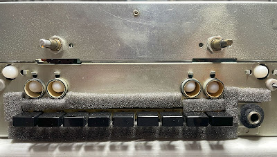
Note that the old foam strips around the push button switches have degraded and falling apart due to age. I replaced them with new foam strips to prevent light leaking through the display.
Original incandescent lamps and crumbly foam strips around pushbutton switches
New warm white LED lamps and new foam strips around pushbutton switches
Output Power Test
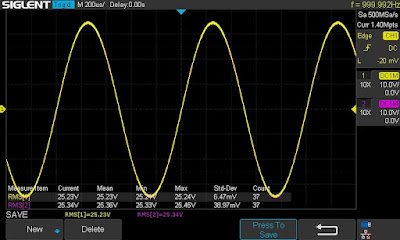
The final output power test was performed at the end of my restoration. The amplifier was loaded with a low inductance 8Ω/100W dummy resistor for each channel. The oscilloscope was connected across the speaker terminals and a sine-wave signal of 1kHz was applied to the AUX jacks. The output sine-wave signal was perfectly symmetrical on both channels with no clipping up to 25.23 VRMS (left channel) and 25.34 VRMS (right channel). It corresponds to the output power of 79.6W on the left channel and 80.3W on the right channel.
Output power test
As usual, all the knobs were cleaned in warm water with dish soap. The front panel was carefully wiped with a piece of damp cloth. All controls have been cleaned with DeoxIT 5% contact cleaner and lubricated with DeoxIT FaderLube 5% spray.
The final result can be seen in the photos below. This unit looks and sounds amazing. Please watch a short demo video at the end of this post. Thank you for reading.
McIntosh MA 6100 - after restoration


_before%20servicing.jpg)
_after%20servicing.jpg)
_before%20servicing.jpg)
_after%20servicing.jpg)
_before%20servicing.jpg)
_after%20servicing.jpg)
_before%20servicing.jpg)
_after%20servicing.jpg)
_before%20servicing.jpg)
_after%20servicing.jpg)
_C317_original.jpg)
_C317_new.jpg)


They are very special! Well done!
ReplyDeleteThank you!
Delete