Unit: Stereo Integrated Amplifier
Manufacturer: Luxman
Model: L-80V
SN: I6507821
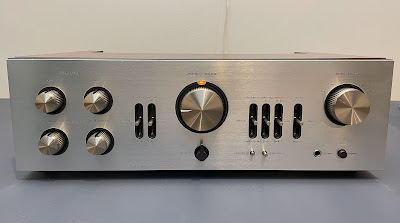
Today I'm showing a gorgeous Luxman L-80V integrated amplifier that came in for restoration. This model was manufactured from 1978 to 1979. It produces 50 watts per channel into 8 ohms with no more than 0.05% total harmonic distortion. The damping factor at 8 ohms is 40. The list price in 1978 was $475.00 (Ref. Stereo Directory & Buying Guide, 1978, page 44).
Main Amplifier, Ripple Filter & Muting Protector Board (PB-891)
Main Amplifier Circuit
The main amplifier circuit has 2 solid tantalum capacitors (C101a, C101b) installed in the signal path and 12 aluminum electrolytic capacitors: C103a, C103b, C104a, C104b, C107a, C107b, C108a, C108b, C111a, C111b, C112, C114.
Both original solid tantalum capacitors were replaced with modern low-leakage Nichicon UKL caps. Two aluminum e-caps with a nominal capacitance of 1uF (C112 and C114) were replaced with high-quality film polyester WIMA caps. And the remaining e-caps were replaced with low-impedance Nichicon UPW/UPM capacitors.
The original e-caps were tested with an Atlas ESR70 capacitance meter; the results are below.
Test results on original capacitors removed from the main amplifier circuit:
C101a: rated capacitance – 10uF, measured – 12uF, ESR – 0.44Ω, deviation: +20%
C101b: rated capacitance – 10uF, measured – 12uF, ESR – 0.62Ω, deviation: +20%
C103a: rated capacitance – 100uF, measured – 121uF, ESR – 0.28Ω, deviation: +21%
C103b: rated capacitance – 100uF, measured – 139uF, ESR – 0.22Ω, deviation: +39%
C104a: rated capacitance – 100uF, measured – 128uF, ESR – 0.18Ω, deviation: +28%
C104b: rated capacitance – 100uF, measured – 125uF, ESR – 0.25Ω, deviation: +25%
C107a: rated capacitance – 33uF, measured – 41uF, ESR – 1.08Ω, deviation: +24%
C107b: rated capacitance – 33uF, measured – 39uF, ESR – 1.12Ω, deviation: +18%
C108a: rated capacitance – 100uF, measured – 127uF, ESR – 0.14Ω, deviation: +27%
C108b: rated capacitance – 100uF, measured – 124uF, ESR – 0.16Ω, deviation: +24%
C111a: rated capacitance – 470uF, measured – 680uF, ESR – 0.22Ω, deviation: +45%
C111b: rated capacitance – 470uF, measured – 594uF, ESR – 0.32Ω, deviation: +26%
C112: rated capacitance – 1uF, measured – 1.1uF, ESR – 2.2Ω, deviation: +10%
C114: rated capacitance – 1uF, measured – 1.0uF, ESR – 2.8Ω, deviation: 0%
Equalizer Amplifier Circuit
The equalizer amplifier has 2 solid tantalum capacitors (C201a, C202b) installed in the input signal path and 2 low-leakage e-caps (C202a, C202b).
The original solid tantalum and low-leakage e-caps were replaced with modern low-leakage Nichicon UKL caps.
Test results on original capacitors removed from the equalizer amplifier circuit:
C201a: rated capacitance – 2.2uF, measured – 2.4uF, ESR – 1.02Ω, deviation: +9%
C201b: rated capacitance – 2.2uF, measured – 2.4uF, ESR – 0.88Ω, deviation: +9%
C202a: rated capacitance – 22uF, measured – 23uF, ESR – 0.42Ω, deviation: +5%
C202b: rated capacitance – 22uF, measured – 22uF, ESR – 0.40Ω, deviation: 0%
Protection Circuit
The protection circuit has 4 aluminum electrolytic capacitors: C601, C602, C603, and C604. All of them were replaced with low-impedance Nichicon UPW/UPM capacitors.
Test results on original capacitors removed from the protection circuit:
C601: rated capacitance – 22uF, measured – 27uF, ESR – 0.62Ω, deviation: +23%
C602: rated capacitance – 220uF, measured – 223uF, ESR – 0.28Ω, deviation: +1%
C603: rated capacitance – 220uF, measured – 278uF, ESR – 0.18Ω, deviation: +26%
C604: rated capacitance – 220uF, measured – 293uF, ESR – 0.24Ω, deviation: +33%
Ripple Filter Circuit
The ripple filter circuit has 8 aluminum electrolytic capacitors: C705, C706, C709, C710, C711, C713, and C714. All of them were replaced with low-impedance Nichicon UPW/UPM capacitors.
Test results on original capacitors removed from the ripple filter circuit:
C705: rated capacitance – 220uF, measured – 215uF, ESR – 0.24Ω, deviation: -2%
C706: rated capacitance – 220uF, measured – 230uF, ESR – 0.26Ω, deviation: +5%
C709: rated capacitance – 100uF, measured – 100uF, ESR – 0.44Ω, deviation: 0%
C710: rated capacitance – 100uF, measured – 97uF, ESR – 0.34Ω, deviation: -3%
C711: rated capacitance – 100uF, measured – 98uF, ESR – 0.41Ω, deviation: -2%
C712: rated capacitance – 47uF, measured – 58uF, ESR – 0.37Ω, deviation: +23%
C713: rated capacitance – 100uF, measured – 98uF, ESR – 0.31Ω, deviation: -2%
C714: rated capacitance – 100uF, measured – 102uF, ESR – 0.34Ω, deviation: +2%
The original speaker protection relay in this amplifier was previously replaced with a new Omron MY2-02-DC24 relay. It is still in great shape and I retained it.
The original trimming resistors were replaced with new Bourns potentiometers.
Main amplifier, ripple filter & muting protector board - before and after
Filter & Boost Amplifier Board (PB-892)
The filter & boost amplifier board has 4 solid tantalum capacitors (C301a, C301b, C308a, C308b) installed in the signal path, and 7 aluminum electrolytic capacitors (C302a, C302b, C304a, C304b, C305, C306a, C306b).
The original solid tantalum capacitors were replaced with modern low-leakage Nichicon UKL caps. The remaining aluminum e-caps were replaced with low-impedance Nichicon UPW capacitors.
Test results on original capacitors removed from the filter & boost amplifier board:
C301a: rated capacitance – 4.7uF, measured – 4.9uF, ESR – 0.46Ω, deviation: +4%
C301b: rated capacitance – 4.7uF, measured – 4.9uF, ESR – 0.86Ω, deviation: +4%
C302a: rated capacitance – 33uF, measured – 38uF, ESR – 1.04Ω, deviation: +15%
C302b: rated capacitance – 33uF, measured – 39uF, ESR – 1.11Ω, deviation: +18%
C304a: rated capacitance – 47uF, measured – 59uF, ESR – 0.98Ω, deviation: +26%
C304b: rated capacitance – 47uF, measured – 59uF, ESR – 0.92Ω, deviation: +26%
C305: rated capacitance – 100uF, measured – 91uF, ESR – 0.28Ω, deviation: -9%
C306a: rated capacitance – 100uF, measured – 136uF, ESR – 0.94Ω, deviation: +36%
C306b: rated capacitance – 100uF, measured – 138uF, ESR – 0.62Ω, deviation: +38%
C308a: rated capacitance – 2.2uF, measured – 2.2uF, ESR – 0.82Ω, deviation: 0%
C308b: rated capacitance – 2.2uF, measured – 2.2uF, ESR – 0.52Ω, deviation: 0%
Filter & boost amplifier board - before and after
Tone Control Amplifier Board (PB-893)
The tone control amplifier board has 4 solid tantalum capacitors (C405a, C405b, C409a, C409b) installed in the signal path, and 3 aluminum electrolytic capacitors (C406a, C406b, C408).
The original solid tantalum capacitors were replaced with modern low-leakage Nichicon UKL caps. The remaining aluminum e-caps were replaced with low-impedance Nichicon UPW capacitors.
Test results on original capacitors removed from the tone control amplifier board:
C405a: rated capacitance – 4.7uF, measured – 4.9uF, ESR – 0.58Ω, deviation: +4%
C405b: rated capacitance – 4.7uF, measured – 4.9uF, ESR – 0.55Ω, deviation: +4%
C406a: rated capacitance – 100uF, measured – 112uF, ESR – 0.48Ω, deviation: +12%
C406b: rated capacitance – 100uF, measured – 115uF, ESR – 0.59Ω, deviation: +15%
C408: rated capacitance – 100uF, measured – 99uF, ESR – 0.28Ω, deviation: -1%
C409a: rated capacitance – 2.2uF, measured – 2.2uF, ESR – 0.66Ω, deviation: 0%
C409b: rated capacitance – 2.2uF, measured – 2.1uF, ESR – 0.82Ω, deviation: -5%
Tone control amplifier board - before and after
DC offset and Bias Adjustments
Be aware, that the service manual has an error for DC offset and bias adjustments. The correct procedure is described below.
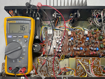
The DC offset on the left and right channels is measured across the speaker terminals (make sure the speaker button is pressed). The DC offset should be adjusted as close to zero volts as possible with the trimming resistor VR101 on each channel.
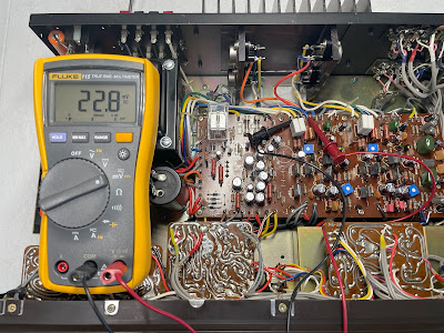
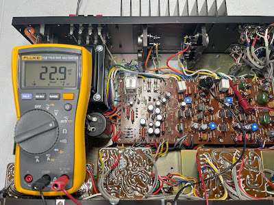
The Bias is measured across two emitter resistors R123 and R124 on each channel. So, the voltmeter should be connected between terminal P103 (+) and terminal P104 (-). The Bias should be adjusted to ~23mV on each channel with the trimming resistor VR102.
DC offset on the left and right channels after restoration
Bias on the left and right channels after restoration
Output Power Test
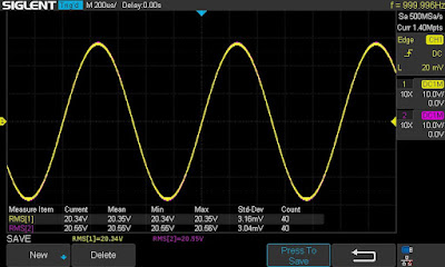
The final output power test was performed at the end of my restoration. The amplifier was loaded with a low inductance 8Ω/100W dummy resistor for each channel. The oscilloscope was connected across the speaker terminals and a sine-wave signal of 1kHz was applied to the AUX jacks. The output sine-wave signal was perfectly symmetrical on both channels with no clipping up to 20.34 VRMS (left channel) and 20.55 VRMS (right channel). It corresponds to the output power of 51.7W on the left channel and 52.8W on the right channel.
Output power test
As usual, all the knobs and the front panel were gently cleaned in warm water with dish soap. All controls have been cleaned with DeoxIT 5% contact cleaner and lubricated with DeoxIT FaderLube 5% spray.
The final result can be seen in the photos below. This integrated amplifier looks and sounds truly amazing. Please watch a short demo video at the end of this post. Thank you for reading.
Luxman L-80V - after restoration

_before%20servicing.jpg)
_after%20servicing.jpg)
_before%20servicing.jpg)
_after%20servicing.jpg)
_before%20servicing.jpg)
_after%20servicing.jpg)



Luxman as always a great unit. Well done! I've got L-507 model that is waiting for service as well
ReplyDeleteThank you, George!
DeleteHey Oleg. Is it okay to run one pair of 4ohm speakers on the L-80V?
ReplyDeleteI would not recommend using 4-ohm speakers on the Luxman L-80V. The L-80V specification only applies to 8-ohm loads.
DeleteThanks for the nice description of the bias adjustment. i am completely new to troubleshooting old luxman. I have just adjusted an own L-80
ReplyDeleteBut it didn't seem to sound very good in the details, maybe there are other components I should change too. Need to troubleshoot one of my friend's L-80 where it blows the fuse immediately when it is switched on. I'm looking forward to spending some evenings on it. Thanks for your good advice :-)