Unit: AM/FM Stereo Receiver
Manufacturer: Sansui
Model: 9090
SN: 825110866
In the golden age of Hi-Fi audio, the Sansui 9090 was one of the most advanced and attractive receivers that any audiophile would want to own. This model was introduced in 1975 and was Sansui's top receiver in the production line: 9090, 8080, 7070, 6060, and 5050. It features two large power meters, signal strength and tuning meters, a power protection circuit with an LED indicator, triple tone control with turnover selectors, two tape deck terminals, a Dolby FM/4-channel adaptor, a wide dynamic range from a precise phono equalization system, a full range of controls, connections for three sets of speaker systems, and an FM Multipath detection system. The Sansui 9090 has a quasi-complementary power stage with eight original Sanken 2SC1116 NPN transistors. It delivers 110 watts per channel into 8 ohms with no more than 0.2% total harmonic distortion. The top cover is made from natural wood, while the low-end models have simulated wood pattern vinyl. The Sansui 9090 is simply a holy grail and one of the best receivers ever made!
As mentioned earlier, the Sansui 9090 was introduced to the market in 1975. In April 1976, Sansui issued a service bulletin addressing a major problem that could occur when both A and B speakers are running simultaneously. To resolve this issue, Sansui recommended modifying the following circuit boards: F-2546 (Power Supply Board), F-2436 (Driver Circuit Board), and F-2547 (Protection Circuit Board). This modification has been implemented at the factory for all units (models 9090 and 8080) since April 1976. The receiver currently on my bench was manufactured in November 1975, and the recommended modification was not performed. I will describe the modification for each board in the following sections.
Power Supply Board (F-2546)
The following modifications on the power supply board (F-2546) have to be done for all units manufactured before April 1976:
1. Four fuses F07, F08, F09, and F10 are originally rated at 6A and must be replaced with 10A fuses.
2. The jumpers in positions F03 and F04 must be removed and new fuse holders must be installed. Two new 10A fuses must be installed in these positions.
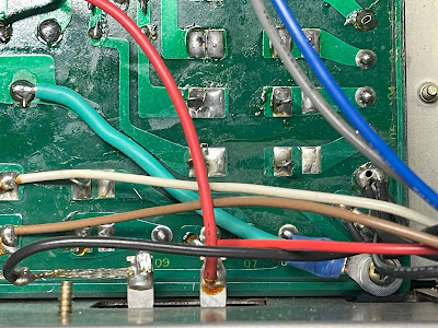
3. A thick, well-conducting wire must be connected between point 03 and the ground lug to improve the ground contact on the PCB F-2546.
4. The jumpers between points 38 and 36, and between points 37 and 35 must be removed.
5. The wire must be connected between point 04 on F-2547 (Protection circuit) to point 35 on F-2546.
6. The wire must be connected between point 03 on F-2547 (Protection circuit) to point 36 on F-2546.
The first item from the list above was very easily solved with new 10A fuses.
The second item was a little tricky. The distance between the fuse clips in positions F03 and F04 is too small to accommodate a conventional 3AG-type fuse (6.3mm x 32mm). So I installed new 2AG fuse clips in these positions and a new 10A 2AG-type (5mm x 20mm) fuse.
I used a piece of 16 AWG wire with a ring terminal to improve the ground contact.
Improved ground contact on the PCB F-2546
The jumpers between points 38 and 36, and between points 37 and 35 were easily removed with a little help from my Hakko FR301 desoldering tool.
Jumpers between points 38 and 36, and between points 37 and 35 (all units manufactured before April 1976)
Jumpers are removed. Don't be confused with the yellow wires. These wires are still soldered to points 38 and 37, respectively. But they were resoldered to the additional foil pads on the PCB (see the picture below for the foil side of the power supply board after servicing)
Now it's time for routine servicing. The power supply board has 5 aluminum electrolytic capacitors (C01, C02, C03, C04, C05) soldered on the front side of the PCB and 2 aluminum e-caps (2.2uF/100V) soldered on the back (foil) side of the PCB.
All capacitors soldered on the front side of this board were replaced with low impedance Nichicon UPW/UPM caps. Two additional e-caps soldered on the back side were replaced with wide temperature range Nichicon UVY caps.
The original e-caps were tested with an Atlas ESR70 capacitance meter; the results are below.
Test results on original capacitors removed from the power supply board:
C01: rated capacitance – 1000uF, measured – 715uF, ESR – 0.08Ω, deviation: -29%
C02: rated capacitance – 220uF, measured – 278uF, ESR – 0.11Ω, deviation: +26%
C03: rated capacitance – 100uF, measured – 112uF, ESR – 0.27Ω, deviation: +12%
C04: rated capacitance – 47uF, measured – 53uF, ESR – 0.36Ω, deviation: +13%
C05: rated capacitance – 100uF, measured – 113uF, ESR – 0.25Ω, deviation: +13%
C (foil side): rated capacitance – 2.2uF, measured – uF, ESR – Ω, deviation: %
C (foil side): rated capacitance – 2.2uF, measured – uF, ESR – Ω, deviation: %
I also replaced all transistors on this board to improve the reliability of the power supply. Below is a list of original and replacement transistors that I have used. A fresh silicone thermal compound (Wakefield-Vette, 120 series) was applied between the new MJE15032G transistor installed in position TR02 and the heat sink.
TR01: NPN, 2SC1211 (original), replaced with a new KSC2383YTA
TR02: NPN, 2SD313 (original), replaced with a new MJE15032G
TR03: NPN, 2SC1211 (original), replaced with a new KSC2383YTA
The potential leakage of the original Zener diode (ZD01) on this board might cause the breakdown of the protection relay as noted in the service bulletin. I replaced it with a new Onsemi 1N5243B (13V/0.5W) Zener diode as a part of preventive maintenance.
Power supply board - before servicing (the driver board is removed)
Power supply board - after servicing
Driver Circuit Board (F-2436)
The following modifications on the driver circuit board (F-2436) have to be done for all units manufactured before April 1976:
1. Check if the two points of coils L01 and L02 are connected by a jumper. If so, then remove the jumper.
2. Two wire-in 7A fuses must be soldered between pins 3 and 4, and between pins 15 and 16, respectively.
This particular PCB (F-2436-1) has no coils. These coils were probably installed in the early days of production.
I soldered two 7A fuses between the corresponding contacts. The body and leads of each fuse were insulated with pieces of heat shrink tubing. Pay attention to this step. New fuses must be securely isolated from other PCB components.
The driver circuit board has 2 low leakage e-caps (C01, C02) installed in the signal path, 2 bi-polar e-caps (C07, C08), and 2 aluminum electrolytic capacitors (C11, C12).
The original low leakage capacitors were replaced with high-quality film polyester WIMA caps. Two bi-polar e-caps were replaced with modern bi-polar Nichicon UEP caps. And two original filtering e-caps (C11, C12) were replaced with low impedance Nichicon UPM capacitors.
Test results on original capacitors removed from the driver circuit board:
C01: rated capacitance – 0.47uF, measured – 0.44uF, ESR – N/A, deviation: -6%
C02: rated capacitance – 0.47uF, measured – 0.43uF, ESR – N/A, deviation: -9%
C07: rated capacitance – 100uF, measured – 118uF, ESR – 0.51Ω, deviation: +18%
C08: rated capacitance – 100uF, measured – 120uF, ESR – 0.36Ω, deviation: +20%
C11: rated capacitance – 100uF, measured – 121uF, ESR – 0.14Ω, deviation: +21%
C12: rated capacitance – 100uF, measured – 123uF, ESR – 0.22Ω, deviation: +23%
The original fusible resistors (R29, R30, R39, R40, R43, R44, R47, R48, R49, R50) on this board were replaced with metal film KOA Speer resistors. One original fusible resistor (R40) was found open. Another one (R43) drifted from the nominal value by more than 14%.
The original trimming resistors were also replaced with new Bourns potentiometers.
Driver circuit board - before and after
Equalizer Circuit Board (F-2541)
The equalizer circuit board has 4 low leakage e-caps (C03, C04, C11, C12) installed in the signal path, and 5 aluminum electrolytic capacitors (C05, C06, C09, C10, C601).
Two original low leakage e-caps (C03, C04) installed in the input signal path were replaced with modern low leakage Nichicon UKL caps. The low leakage e-caps (C11, C12) installed in the output signal path were replaced with film polyester WIMA caps. The remaining aluminum e-caps except C601 were replaced with low impedance Nichicon UPW/UHE caps. The e-cap C601 was replaced with a film polyester WIMA cap.
Test results on original capacitors removed from the equalizer circuit board:
C03: rated capacitance – 3.3uF, measured – 2.9uF, ESR – 2.4Ω, deviation: -12%
C04: rated capacitance – 3.3uF, measured – 2.9uF, ESR – 2.8Ω, deviation: -12%
C05: rated capacitance – 470uF, measured – 553uF, ESR – 0.04Ω, deviation: +18%
C06: rated capacitance – 470uF, measured – 552uF, ESR – 0.09Ω, deviation: +17%
C09: rated capacitance – 47uF, measured – 56uF, ESR – 0.71Ω, deviation: +19%
C10: rated capacitance – 47uF, measured – 54uF, ESR – 0.68Ω, deviation: +15%
C11: rated capacitance – 1uF, measured – 1uF, ESR – 3.3Ω, deviation: 0%
C12: rated capacitance – 1uF, measured – 1uF, ESR – 3.6Ω, deviation: 0%
C601: rated capacitance – 1uF, measured – 1.2uF, ESR – 3.4Ω, deviation: +20%
Equalizer circuit board - before and after
Accessory Switch Board (F-2542)
This board has only one aluminum electrolytic capacitor C601. I replaced it with a low impedance Nichicon UPW cap.
Test results on original capacitors removed from the accessory switch board:
C601: rated capacitance – 33uF, measured – 40uF, ESR – 0.31Ω, deviation: +21%
Accessory switch board - before and after
Tone Control Board (F-2543)
The tone control board (F-2543) has 4 low leakage e-caps (C603, C604, C607, C611) and 3 aluminum electrolytic capacitors (C606, C609, C610).
Two original low leakage e-caps (C603, C604) with a rated capacitance of 2.2uF were replaced with film polyester WIMA caps. The other 2 low leakage e-caps were replaced with modern low leakage Nichicon UKL caps. The remaining aluminum e-caps were replaced with low impedance Nichicon UPW/UPM caps.
Test results on original capacitors removed from the tone control board (F-2543):
C603: rated capacitance – 2.2uF, measured – 1.9uF, ESR – 3.2Ω, deviation: -14%
C604: rated capacitance – 2.2uF, measured – 1.9uF, ESR – 3.9Ω, deviation: -14%
C606: rated capacitance – 47uF, measured – 51uF, ESR – 1.77Ω, deviation: +9%
C607: rated capacitance – 1uF, measured – 1uF, ESR – 4.1Ω, deviation: 0%
C609: rated capacitance – 100uF, measured – 114uF, ESR – 0.11Ω, deviation: +14%
C610: rated capacitance – 470uF, measured – 536uF, ESR – 0.12Ω, deviation: +14%
C611: rated capacitance – 4.7uF, measured – 5.1uF, ESR – 2.1Ω, deviation: +9%
The original 2SC1313 transistor installed in position TR601 is on my list of transistors that are prone to failure. I replaced it with a new low-noise Fairchild KSC1845 transistor. Watch the pinout on replacement transistors. The original transistor is BCE and the new one is ECB.
Tone control board (F-2543) - before and after
Tone Control Board (F-2544)
The tone control board (F-2544) has 8 low leakage e-caps (C01, C02, C05, C06, C27, C28, C31, C32) installed in the signal path, and 6 aluminum electrolytic capacitors (C09, C10, C33, C34, C601, C602).
The original low leakage capacitors with a rated capacitance of 1uF and 2.2uF were replaced with film polyester WIMA caps. The other 4 low leakage e-caps were replaced with modern low leakage Nichicon UKL caps. And the remaining aluminum e-caps were replaced with low impedance Nichicon UPW caps.
Test results on original capacitors removed from the tone control board (F-2544):
C01: rated capacitance – 1uF, measured – 0.9uF, ESR – 4.6Ω, deviation: -10%
C02: rated capacitance – 1uF, measured – 0.9uF, ESR – 3.7Ω, deviation: -10%
C05: rated capacitance – 10uF, measured – 11uF, ESR – 1.87Ω, deviation: +10%
C06: rated capacitance – 10uF, measured – 11uF, ESR – 3.1Ω, deviation: +10%
C09: rated capacitance – 47uF, measured – 54uF, ESR – 0.84Ω, deviation: +15%
C10: rated capacitance – 47uF, measured – 52uF, ESR – 0.91Ω, deviation: +11%
C27: rated capacitance – 2.2uF, measured – 1.9uF, ESR – 3.9Ω, deviation: -14%
C28: rated capacitance – 2.2uF, measured – 1.9uF, ESR – 2.6Ω, deviation: -14%
C31: rated capacitance – 10uF, measured – 11uF, ESR – 1.44Ω, deviation: +10%
C32: rated capacitance – 10uF, measured – 11uF, ESR – 1.12Ω, deviation: +10%
C33: rated capacitance – 220uF, measured – 225uF, ESR – 0.37Ω, deviation: +2%
C34: rated capacitance – 220uF, measured – 226uF, ESR – 0.44Ω, deviation: +3%
C601: rated capacitance – 470uF, measured – 574uF, ESR – 0.31Ω, deviation: +22%
C602: rated capacitance – 220uF, measured – 252uF, ESR – 0.22Ω, deviation: +15%
The prone-to-failure 2SC1313 transistor installed in positions TR01 & TR02 was replaced with a new low-noise Fairchild KSC1845 transistor. Watch the pinout on replacement transistors. The original transistor is BCE and the new one is ECB.
Tone control board (F-2544) - before and after
Filter & Muting Circuit Board (F-2545)
The filter & muting circuit board has only 2 low leakage e-caps (C05, C06) installed in the signal path. I replaced them with film polyester WIMA caps.
Test results on original capacitors removed from the filter & muting circuit board:
C05: rated capacitance – 2.2uF, measured – 1.8uF, ESR – 2.3Ω, deviation: -18%
C06: rated capacitance – 2.2uF, measured – 1.9uF, ESR – 2.2Ω, deviation: -14%
Filter & muting circuit board - before and after
Protection Circuit Board (F-2547)
The following modifications on the protection circuit board (F-2547) have to be done for all units manufactured before April 1976:
1. Two resistors (R13 & R14) rated at 10Ω, 1W have to be replaced with resistors of 4.7Ω, 1/2W.
2. The jumper connecting some relay contacts to the ground has to be removed.
To address the first issue, I replaced the original resistors R13 and R14 with metal film KOA Speer resistors (4.75Ω, 1/2W). The jumper connecting some relay contacts to the ground was also removed (refer to the picture below, the jumper is soldered between the relay's contact and resistor R06).
The protection circuit board has 2 bi-polar capacitors (C05, C12) and 6 aluminum electrolytic capacitors (C01, C02, C03, C04, C06, C07).
The original bi-polar capacitor C05 was replaced with a modern bi-polar Nichicon UEP cap. Another bi-polar capacitor C12 and the e-caps C04, C06, and C07 with a nominal capacitance of 1uF were replaced with film polyester WIMA caps. The remaining aluminum e-caps were replaced with low impedance Nichicon UPW caps.
Test results on original capacitors removed from the protection circuit board:
C01: rated capacitance – 33uF, measured – 38uF, ESR – 0.34Ω, deviation: +15%
C02: rated capacitance – 220uF, measured – 235uF, ESR – 0.14Ω, deviation: +7%
C03: rated capacitance – 470uF, measured – 498uF, ESR – 0.09Ω, deviation: +6%
C04: rated capacitance – 1uF, measured – 1.1uF, ESR – 2.1Ω, deviation: +10%
C05: rated capacitance – 47uF, measured – 50uF, ESR – 1.1Ω, deviation: +6%
C06: rated capacitance – 1uF, measured – 1.1uF, ESR – 2.4Ω, deviation: +10%
C07: rated capacitance – 1uF, measured – 1.2uF, ESR – 2.3Ω, deviation: +20%
C12: rated capacitance – 1uF, measured – 1uF, ESR – 3.6Ω, deviation: 0%
The original trimming resistors (VR01 and VR02) used to adjust the power meters were replaced with new Bourns potentiometers.
Finally, the original protection relay was replaced with a new Omron relay to improve overall reliability.
Protection circuit board - before and after
Power Supply Board (F-2431)
The power supply board (F-2431) has 3 aluminum electrolytic capacitors: C01, C02, and C901. All of them were replaced with low impedance Nichicon UPW/UPM caps.
Test results on original capacitors removed from the power supply (F-2431) board:
C01: rated capacitance – 220uF, measured – 221uF, ESR – 0.31Ω, deviation: 0%
C02: rated capacitance – 100uF, measured – 111uF, ESR – 0.43Ω, deviation: +11%
C901: rated capacitance – 470uF, measured – 507uF, ESR – 0.19Ω, deviation: +8%
Power supply board (F-2431) - before and after
Multi-Path Circuit Board (F-2550)
The multi-path circuit board has 3 aluminum electrolytic capacitors: C01, C03, and C04.
The original e-cap C01 with a nominal capacitance of 1uF was replaced with a film polyester WIMA cap. The remaining e-caps were replaced with low impedance Nichicon UPW caps. Pay attention to the polarity of the e-cap C04 (10uF/16V). The polarity on the silkscreen is backward!
Test results on original capacitors removed from the multi-path circuit board:
C01: rated capacitance – 1uF, measured – 1.2uF, ESR – 2.1Ω, deviation: +20%
C03: rated capacitance – 4.7uF, measured – 5.5uF, ESR – 2.6Ω, deviation: +17%
C04: rated capacitance – 10uF, measured – 11uF, ESR – 3.8Ω, deviation: +10%
The original 2SC711 NPN transistor installed in positions TR01 and TR02 is on my list of transistors that are prone to failure. I replaced it with a new low-noise Fairchild KSC1845 transistor. Watch the pinout on replacement transistors. The original transistor is BCE and the new one is ECB.
Multi-path circuit board - before and after
Power Transistors
The original Sanken 2SC1116A power transistors were removed from the chassis, degreased with isopropanol, and tested with an Atlas DCA55 semiconductor analyzer. Each pair of transistors is still matched very well by the current gain and base-emitter voltage. I mounted all the power transistors back and applied fresh thermal paste. The old thermal pads were also replaced with new Mica ones.
Test results on original Sanken 2SC1116A power transistors:
TR701: hfe - 48, Vbe - 0.585V
TR702: hfe - 48, Vbe - 0.583V
TR703: hfe - 58, Vbe - 0.592V
TR704: hfe - 53, Vbe - 0.591V
TR705: hfe - 45, Vbe - 0.596V
TR706: hfe - 46, Vbe - 0.597V
TR707: hfe - 55, Vbe - 0.591V
TR708: hfe - 51, Vbe - 0.594V
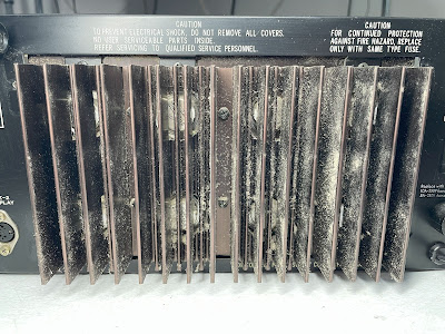
Power transistors - before servicing, very dusty heat sink
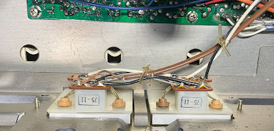
Power transistors - before servicing, the heat sink removed
Power transistors - new Mica pads and fresh thermal paste
Dial Lamps
To replace the dial lamps one should remove two small screws from the top of the chassis that hold the plastic lamp reflector. I replaced the original incandescent lamps with warm white LED lamps to maintain the original look and decrease heat.
New warm white LED lamps
Signal Strength and Tuning Meter Lamps
I do prefer to use warm white LED lamps in vintage receivers because their color temperature is close to that of incandescent lamps. In addition, the LED lamps produce a lower amount of heat in comparison to the incandescent lamps thereby protecting the plastic parts of lamp holders/reflectors from overheating. However, I found the warm white LED lamps to be too bright if they are installed behind the meters. So, I decided to stick with the original design and installed new incandescent lamps here. The meter lamps can be easily replaced with LED lamps in the future if necessary.
Power Meter Lamps
The power meter lamps are very difficult to replace in the Sansui 9090 due to the limited space to work with. In addition, original rubber bushings often wear out over time due to overheating. Initially, I tried to replace the old rubber bushings with modern ones available on the market. However, modern bushings do not hold lamps well due to their primitive design compared to the original bushings. Fortunately, the original rubber bushings in this unit are still in very good condition and I was able to use them again without loss of quality. In any case, replacing power meter lamps in Sansui 9090 is very tedious work.
Power meter lamps - before and after
Filter Capacitors
Two main filter capacitors were tested with Atlas ESR70 capacitance meter (in-circuit test). Both caps are still within the factory capacitance tolerance and have almost zero ESR. So, I didn't change them. In general, the filter capacitors rarely fail in vintage gears, and I usually don't replace them unless their ESR is high.
In-circuit test on two filter capacitors - both are still in spec
C703: rated capacitance – 6800uF, measured – 6887uF, ESR – 0.04Ω, deviation: +1%
C704: rated capacitance – 6800uF, measured – 6683uF, ESR – 0.02Ω, deviation: -2%
DC offset and Idling Current Adjustments
The DC offset is measured across speaker terminals on each channel. It should be adjusted as close to zero volts as possible with the trimming resistors VR01 and VR02, respectively.
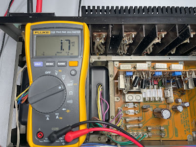
To adjust the idling current one should remove the fuse from the left (right) channel and connect the DC ammeter between the terminals of the fuse holder. Then the idling current should be adjusted to 50mA +/- 1mA with the trimming resistor VR03 (VR04).
DC offset on the left and right channels after restoration
Idling current on the left and right channels after restoration
Output Power Test
The final output power test was performed at the end of my restoration. The receiver was loaded with a low inductance 8Ω/100W dummy resistor for each channel. The oscilloscope was connected across the speaker terminals and a sine-wave signal of 1kHz was applied to the AUX jacks. The output sine-wave signal was perfectly symmetrical on both channels with no clipping up to 29.38 VRMS (left channel) and 29.04 VRMS (right channel). It corresponds to the output power of 107.9W on the left channel and 105.4W on the right channel. I was not able to test this receiver above its 110W rating simply because my current dummy resistor can only dissipate 100W max (I probably need to invest some money and buy additional dummy resistors that can dissipate around 200W).
Output power test
As usual, all the knobs and the front panel were gently cleaned in warm water with dish soap. All controls have been cleaned with DeoxIT 5% contact cleaner and lubricated with DeoxIT FaderLube 5% spray. The wood case was treated with Howard's Restor-A-Finish.
The final result can be seen in the photos below. This receiver from the 70s is a real gem - beautiful looks, solid design, and amazing sound. Please watch a short demo video at the end of this post. Thank you for reading.
Sansui 9090 - after restoration


_jumper%20between%20points%2038%20&%2036_before%20servicing.jpg)
_jumper%20between%20points%2035%20&%2037_before%20servicing.jpg)
_no%20jumper%20between%20points%2038%20&%2036_after%20servicing.jpg)
_no%20jumper%20between%20points%2035%20&%2037_after%20servicing.jpg)
_front%20side_before%20servicing.jpg)
_foil%20side_before%20servicing.jpg)
_front%20side_after%20servicing.jpg)
_foil%20side_after%20servicing.jpg)
_prior%20April%201976_before%20servicing.jpg)
_prior%20April%201976_after%20servicing.jpg)
_before%20servicing.jpg)
_after%20servicing.jpg)
_before%20servicing.jpg)
_after%20servicing.jpg)
_before%20servicing.jpg)
_after%20servicing.jpg)
_before%20servicing.jpg)
_after%20servicing.jpg)
_before%20servicing.jpg)
_after%20servicing.jpg)
_before%20servicing.jpg)
_after%20servicing.jpg)
_before%20servicing.jpg)
_after%20servicing.jpg)
_before%20servicing.jpg)
_after%20servicing.jpg)


The BEST
ReplyDeleteBack in the "Pacific Stereo" years, I've sold them all. THE CLEANEST and best balanced unit of the Sansui stereo-receiver line. SOLID wood cab; no wood-vinyl. 110 watts a side is more than enough.
Those who need more punch from hungrier speakers will choose Sansui's beautiful separates.
Sansui's designs up to this model were gorgeous; especially their 4-channel units. Sansui's receiver design and materials strayed wayward after this 9090 build. The succession of the 9090bd with the "rectangular black PLASTIC power button" was a sloppy indicator. Who thought that made any sense?
Hang on to that one and enjoy, sir; it is a GRAIL.
Absolutely beautiful job!
ReplyDeleteI have one as well and need it refurbed.
What do you charge?
Thx
Roger F