Unit: AM/FM Stereo Receiver
Manufacturer: Realistic
Model: STA-120B
SN: 06019760
Another vintage Realistic stereo receiver came on my bench for restoration. The Realistic STA-120B (Cat. No. 31-2042) was produced from 1972 to 1973. It produces 30 watts per channel into 8 ohms with no more than 0.8% total harmonic distortion. The retail price in the first year of sale was $279.95 (Ref. Radio Shack Catalog, 1972, ver.1, page 10).
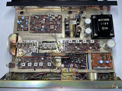
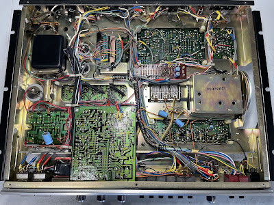
Realistic STA-120B - inside view before restoration
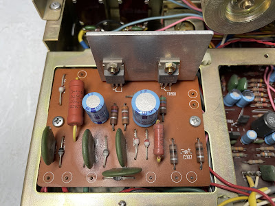
Power Supply Board
The power supply board has only 2 aluminum electrolytic capacitors: C901 and C906. I replaced them with low impedance Nichicon UPW/UPM caps.
The original e-caps were tested with an Atlas ESR70 capacitance meter; the results are below.
Test results on original capacitors removed from the power supply board:
C901: rated capacitance – 100uF, measured – 113uF, ESR – 0.16Ω, deviation: +13%
C906: rated capacitance – 100uF, measured – 127uF, ESR – 0.29Ω, deviation: +27%
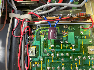
The original Hitachi 2SC1061 regulating transistor is installed in positions TR901 and TR902. This transistor is on my list of transistors that are prone to failure. I replaced this transistor with a new Fairchild MJE15032G. The MJE15032G is a "bulletproof" transistor and can dissipate twice the power of the original transistor: 50W vs. 25W.
Power supply board - before and after
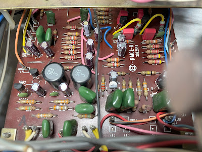
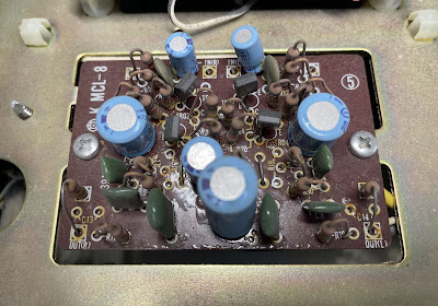
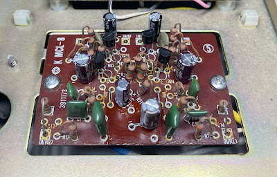
Tone Amplifier Board
The tone amplifier board has 17 aluminum electrolytic capacitors: C603, C604, C611, C612, C613, C614, C615, C616, C617, C618, C631, C632, C633, C634, C637, C638, and C639. I replaced the e-caps C631, C632, C637, and C638 installed in the signal path with high-quality film polyester WIMA caps. The remaining e-caps were replaced with low impedance Nichicon UPW/UPM caps. Note, that almost all original electrolytic capacitors from this board fail for the factory tolerance spec of +/- 20%.
Test results on original capacitors removed from the tone amplifier board:
C603: rated capacitance – 10uF, measured – 15uF, ESR – 1.32Ω, deviation: +50%
C604: rated capacitance – 10uF, measured – 15uF, ESR – 1.46Ω, deviation: +50%
C611: rated capacitance – 10uF, measured – 15uF, ESR – 1.85Ω, deviation: +50%
C612: rated capacitance – 10uF, measured – 14uF, ESR – 1.62Ω, deviation: +40%
C613: rated capacitance – 10uF, measured – 13uF, ESR – 1.78Ω, deviation: +30%
C614: rated capacitance – 10uF, measured – 13uF, ESR – 1.41Ω, deviation: +30%
C615: rated capacitance – 4.7uF, measured – 5.9uF, ESR – 2.2Ω, deviation: +26%
C616: rated capacitance – 4.7uF, measured – 6.3uF, ESR – 2.9Ω, deviation: +34%
C617: rated capacitance – 10uF, measured – 14uF, ESR – 1.62Ω, deviation: +40%
C618: rated capacitance – 10uF, measured – 13uF, ESR – 1.73Ω, deviation: +30%
C631: rated capacitance – 1uF, measured – 1.2uF, ESR – 6.2Ω, deviation: +20%
C632: rated capacitance – 1uF, measured – 1.1uF, ESR – 5.7Ω, deviation: +10%
C633: rated capacitance – 4.7uF, measured – 6.5uF, ESR – 2.3Ω, deviation: +38%
C634: rated capacitance – 4.7uF, measured – 6.4uF, ESR – 2.4Ω, deviation: +36%
C637: rated capacitance – 1uF, measured – 1.2uF, ESR – 4.8Ω, deviation: +20%
C638: rated capacitance – 1uF, measured – 1.3uF, ESR – 5.1Ω, deviation: +30%
C639: rated capacitance – 100uF, measured – 114uF, ESR – 0.1Ω, deviation: +14%
The six NPN transistors (TR601 to TR606) installed on this board are the notorious 2SC458 transistors. This transistor has different types of failure modes: leakage, noise, and/or static. I replaced every 2SC458 transistor with a modern low-noise Fairchild KSC1845. Keep an eye on the pinout of the replaced transistors when servicing this board. The original transistor is BCE and the new one is ECB.
Tone amplifier board - before and after
Equalizer Amplifier Board
The equalizer amplifier board has 6 aluminum electrolytic capacitors: C501, C502, C509, C510, C515, and C516. Two ordinary aluminum e-caps C501 and C502 installed in the signal path were replaced with modern low leakage Nichicon UKL caps to reduce the noise generated in the circuit. The remaining e-caps were replaced with low impedance Nichicon UPW caps. Note, that the original e-caps C501 and C502 installed in the signal path have a deviation of more than 70% from the nominal capacitance.
This board also has 4 notorious 2SC458 transistors installed in positions TR501 thru TR504. These were replaced with a modern low-noise Fairchild KSC1845 transistors.
Test results on original capacitors removed from the equalizer amplifier board:
C501: rated capacitance – 10uF, measured – 19uF, ESR – 1.99Ω, deviation: +90%
C502: rated capacitance – 10uF, measured – 17uF, ESR – 2.91Ω, deviation: +70%
C509: rated capacitance – 100uF, measured – 134uF, ESR – 0.51Ω, deviation: +34%
C510: rated capacitance – 100uF, measured – 137uF, ESR – 0.43Ω, deviation: +37%
C515: rated capacitance – 47uF, measured – 68uF, ESR – 0.36Ω, deviation: +45%
C516: rated capacitance – 22uF, measured – 27uF, ESR – 1.14Ω, deviation: +23%
Equalizer amplifier board - before and after
Main Amplifier Board
Like the Realistic STA-180, the STA-120B has two main amplifier boards. And each board is fixed in a slot. This greatly simplifies the servicing of the main amplifier.
Each board has 4 aluminum electrolytic capacitors (C802, C803, C804, and C808). All of them were replaced with low impedance Nichicon UPW/UPM caps.
Test results on original capacitors removed from the main amplifier board:
Left channel
C802: rated capacitance – 100uF, measured – 120uF, ESR – 0.06Ω, deviation: +20%
C803: rated capacitance – 220uF, measured – 283uF, ESR – 0.22Ω, deviation: +29%
C804: rated capacitance – 47uF, measured – 66uF, ESR – 0.32Ω, deviation: +40%
C808: rated capacitance – 100uF, measured – 120uF, ESR – 0.09Ω, deviation: +20%
Right channel
C802: rated capacitance – 100uF, measured – 125uF, ESR – 0.08Ω, deviation: +25%
C803: rated capacitance – 220uF, measured – 291uF, ESR – 0.38Ω, deviation: +32%
C804: rated capacitance – 47uF, measured – 74uF, ESR – 0.51Ω, deviation: +57%
C808: rated capacitance – 100uF, measured – 123uF, ESR – 0.06Ω, deviation: +23%
Main amplifier boards from the left and right channels - before restoration
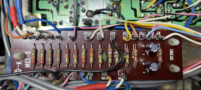
Sub Board
This board has only 2 aluminum electrolytic capacitors: C4 and C5. I replaced them with low impedance Nichicon UPW caps.
Test results on original capacitors removed from the sub board:
C4: rated capacitance – 47uF, measured – 61uF, ESR – 1.16Ω, deviation: +30%
C5: rated capacitance – 47uF, measured – 63uF, ESR – 1.08Ω, deviation: +34%
Sub board - before and after
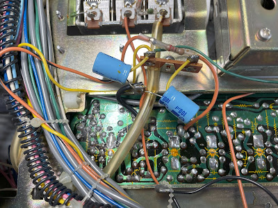
Off Board Capacitors
The original filtering electrolytic capacitors C13, C14, and C18 were replaced with low impedance Nichicon UPW/UPM caps.
Test results on original filtering capacitors:
C13: rated capacitance – 100uF, measured – 164uF, ESR – 0.34Ω, deviation: +64%
C14: rated capacitance – 100uF, measured – 170uF, ESR – 0.38Ω, deviation: +70%
C18: rated capacitance – 220uF, measured – 288uF, ESR – 0.15Ω, deviation: +31%
Original and new filtering e-caps C13 & C14
Main Filter and Coupling Capacitors
I don't usually replace filter capacitors in vintage gears unless their ESR is high or the capacitance tolerance is more than +/-10%. In this unit, the main filter capacitor C10 still has a low ESR of 0.03Ω but the measured capacitance is more than 20% above the nominal one. So, I replaced it with a new Nichicon LKG e-cap. Both original C8 and C9 coupling capacitors were also replaced with Nichicon LKG capacitors. The LKG series was designed for high-grade audio equipment and, in my opinion, is the best replacement for the original filter and/or coupling capacitors on the market. The new Nichicon LKG e-caps are the same diameter as the original ones but shorter. Thus, the same clamps can be used to attach them to the chassis.
Test results on the original filter and coupling capacitors:
C8: rated capacitance – 1000uF, measured – 1440uF, ESR – 0.02Ω, deviation: +44%
C9: rated capacitance – 1000uF, measured – 1286uF, ESR – 0.03Ω, deviation: +29%
C10: rated capacitance – 2200uF, measured – 2708uF, ESR – 0.03Ω, deviation: +23%
Main filter and coupling capacitors - new Nichicon LKG series
Power Transistors
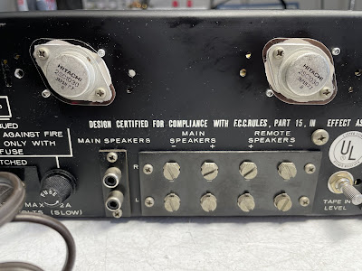
Four power transistors are located on the rear panel and covered with a perforated panel. The case serves as a heat sink. This design makes servicing the power transistors a very simple task.
I removed the original Hitachi 2SC1030 power transistors from the chassis, degreased with isopropanol, and tested them with an Atlas DCA55 semiconductor analyzer. The measured DC current gain on all transistors met the specifications in the datasheet. Each pair of transistors was also very well matched within ~6%. Keep in mind that this unit is 50 old! I mounted all the power transistors back and applied fresh thermal paste. The old thermal pads were also replaced with new Mica ones.
Test results on original Hitachi 2SC1030 power transistors:
TR1: hfe - 48, Vbe - 0.593V
TR2: hfe - 51, Vbe - 0.587V
TR3: hfe - 62, Vbe - 0.585V
TR4: hfe - 58, Vbe - 0.586V
Original power transistors with new Mica pads and fresh thermal paste
Dial and Meter Lamps
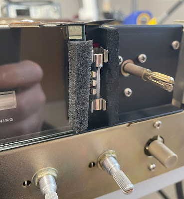
The dial and meter lamps in this unit have been already replaced with warm white LED lamps by the owner.
New warm white LED meter lamps
New warm white LED dial lamps
Main Amplifier Adjustment
To adjust an equal clipping on each channel, I connected my oscilloscope across the speaker terminals and applied a sine-wave signal of 1 kHz to the AUX jacks. A low inductance 8Ω/100W dummy resistor was used as an output load. Then, the trimming resistor VR801 was adjusted for equal clipping of the sine-wave signal.
Output Power Test
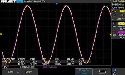
The final output power test was performed at the end of my restoration. The receiver was loaded with a low inductance 8Ω/100W dummy resistor for each channel. The oscilloscope was connected across the speaker terminals and a sine-wave signal of 1kHz was applied to the AUX jacks. The output sine-wave signal was perfectly symmetrical on both channels with no clipping up to 13.30 VRMS (left channel) and 13.39 VRMS (right channel). It corresponds to the output power of 22.1W on the left channel and 22.4W on the right channel.
Output power test
As usual, all the knobs and the front panel were gently cleaned in warm water with dish soap. All controls have been cleaned with DeoxIT 5% contact cleaner and lubricated with DeoxIT FaderLube 5% spray.
The final result can be seen in the photos below. Please watch a short demo video at the end of this post. Thank you for reading.
Realistic STA-120B - after restoration












Great to see this Realistic receiver getting the Go Over! I have one that belonged to my father. It's in fine physical shape, having been sitting in the same house and room since new.
ReplyDeleteThanks for the detailed guidance pointing the path to restore and update this beloved piece of equipment!
It looks like Hitachi built this receiver as the Hitachi emblem is on the PC boards
ReplyDeleteYes, I think so too.
DeleteBy chance, do you have a hi-resolution schematic for this unit?
ReplyDeleteAll I can find on-line is of poor resolution at best.
The owners manual likely came with on but it needs a good scan to make readable.
Yes, I have it. Please email me at repair@olegvintageaudio.com.
DeleteHello Oleg,
ReplyDeleteThank you for posting this restoration of the Realistic STA-120B Receiver, (I printed it) I purchased a Realistic STA-120 Receiver in 1969 for around $300, I still use it every day. I have just purchased two (2) of the Realistic STA-120B Receivers last week on eBay for about $200 each, one was very nice, and the other was very good (otherwise rather dirty & a little dinged). I have not tried them out yet, but I am glad to have gotten them for the price. I don't believe you can buy compatible quality stereo receivers like these for what you get today, (I could be wrong) and at much higher prices, I'm sure. Thanks again for this posting, I look forward to seeing more.
Best Regards,
Joseph Comeau
Lynn, Massachusetts