Unit: AM/FM Stereo Receiver
Manufacturer: Marantz
Model: 2285B
SN: 8XE150318
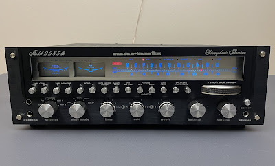
Today I'm showcasing a Marantz 2285B vintage receiver that came in for restoration. This unit is a real gem with an original black faceplate (European version with a universal power transformer). The owner bought it about 12-14 years ago and was lucky enough to find this unit in almost perfect cosmetic condition.
The Marantz 2285B is a high-end model in the 22XXB production line. It was manufactured from 1977 to 1980. It produces 85 watts per channel into 8 ohms with no more than 0.05% total harmonic distortion. The optional walnut veneer cabinet for this model is WC-122.
Servicing Marantz 2285B might be challenging for those without experience and/or the right tools. So, just be aware of that if you want to service this model yourself.
Main Amplifier Board (P700)
The main power amplifier board is mounted directly on the heatsink with 8 power transistors. The entire unit can be easily removed from the chassis for servicing. This thoughtful engineering design makes life easier for technicians.
Main amplifier board - removed from the chassis
This board has 4 low leakage electrolytic capacitors (C701, C705, C720, C724) and 6 aluminum e-caps (C704, C712, C713, C723, C731, C732). The original low leakage e-caps were replaced with modern low leakage Nichicon UKL caps. And, the remaining aluminum e-caps were replaced with low impedance Nichicon UPW caps.
Test results on original capacitors removed from the main amplifier board:
C701: rated capacitance – 2.2uF, measured – 1.9uF, ESR – 5.6Ω, deviation: -14%
C704: rated capacitance – 10uF, measured – 11uF, ESR – 1.02Ω, deviation: +10%
C705: rated capacitance – 100uF, measured – 103uF, ESR – 0.36Ω, deviation: +3%
C712: rated capacitance – 10uF, measured – 12uF, ESR – 1.91Ω, deviation: +20%
C713: rated capacitance – 10uF, measured – 12uF, ESR – 2.4Ω, deviation: +20%
C720: rated capacitance – 2.2uF, measured – 1.8uF, ESR – 5.9Ω, deviation: -18%
C723: rated capacitance – 10uF, measured – 11uF, ESR – 0.66Ω, deviation: +10%
C724: rated capacitance – 100uF, measured – 102uF, ESR – 0.46Ω, deviation: +2%
C731: rated capacitance – 10uF, measured – 12uF, ESR – 2.6Ω, deviation: +20%
C732: rated capacitance – 10uF, measured – 12uF, ESR – 2.1Ω, deviation: +20%
The first stage of the main amplifier circuit is a differential amplifier consisting of two amplifying transistors with a common emitter: Q701/Q702 (left channel) and Q731/Q732 (right channel). The original NPN transistors installed in these positions are 2SC1775A. These transistors are not on my list of infamous transistors that are prone to failure. But I decided to unsolder the original transistors and test them to make sure that they are still well matched by the current gain. As I mentioned many times in my previous posts, two transistors installed in a differential amplifier must be precisely matched to work properly in the circuit. So, it always makes sense to test the original transistors installed in the differential amplifier.
Testing showed that both pairs of 2SC1775As are matched within ~7% in terms of current gain. It is not perfect but still acceptable for 40+ years old transistors. Ideally, two transistors should be matched as close as possible, usually within 1-2%. So, I decided to replace each pair of original 2SC1775A transistors with new close matched pair of modern low-noise Fairchild KSC1845s. As can be seen below, each pair of KSC1845 was carefully matched by current gain and base-emitter voltage.
I put a slight smear of new thermal paste on one face of KSC1845 and pressed both transistors together. A piece of heat shrink tubing was used to hold them together mechanically as in the original transistors.
The original 2SC1775A transistors installed in positions Q703 and Q733 were also replaced with new Fairchild KSC1845s.
Test results on original 2SC1775A transistors
Q701 (left channel): hfe - 448, Vbe - 0.770V
Q702 (left channel): hfe - 478, Vbe - 0.769V
Q731 (right channel): hfe - 566, Vbe - 0.776V
Q732 (right channel): hfe - 529, Vbe - 0.775V
Test results on new KSC1845 transistors
Q701 (left channel): hfe - 418, Vbe - 0.756V
Q702 (left channel): hfe - 418, Vbe - 0.755V
Q731 (right channel): hfe - 418, Vbe - 0.755V
Q732 (right channel): hfe - 419, Vbe - 0.755V
Original and new transistors Q701/Q702, Q731/Q732 - thermally and mechanically bonded
Transistor 2SC1775A is a complementary pair with 2SA872A. These PNP transistors are installed in positions Q704/Q705 (left channel) and Q734/Q735 (right channel). So, it makes sense to replace the original 2SA872A transistors as well. I replaced each 2SA872A with a modern Fairchild KSA992 which is a complementary pair with KSC1845.
Main amplifier board - before and after
Power Transistors
All power transistors were removed, degreased, and tested with an Atlas DCA55 semiconductor analyzer. According to the datasheet, the measured current gain on all transistors was in spec.
However, it should be noted that the Atlas DCA55 Semiconductor Analyzer provides accurate DC gain readings only on low-power transistors. A high-power transistor requires a much higher collector current and collector-emitter voltage to accurately measure its current gain. However, it is still a handy device for comparing transistors of a similar type for gain matching or fault-finding.
I applied a fresh thermal compound and replaced the old thermal pads with new Mica ones which is always a good idea when working on any vintage receiver. The old grease can frequently dry, causing the transistors to suffer from poor heat dissipation. This can result in overheating and the destruction of the device.
Original power transistors
With new Mica pads
Power Supply Board (P800)
I recommend leaving the main amplifier unit unmounted from the chassis while servicing the power supply board. Otherwise, servicing this board will be very difficult due to limited access to the back (foil) side.
The power supply board has 14 aluminum electrolytic capacitors: C801, C802, C803, C804, C806, C809, C810, C812, C813, C815, C817, C818, C819, C820. I replaced them with low impedance Nichicon UPW/UPM caps.
Test results on original capacitors removed from the power supply board:
C801: rated capacitance – 470uF, measured – 461uF, ESR – 0.01Ω, deviation: -2%
C802: rated capacitance – 330uF, measured – 293uF, ESR – 0.06Ω, deviation: -11%
C803: rated capacitance – 100uF, measured – 105uF, ESR – 0.37Ω, deviation: +5%
C804: rated capacitance – 47uF, measured – 52uF, ESR – 0.22Ω, deviation: +11%
C806: rated capacitance – 10uF, measured – 12uF, ESR – 0.98Ω, deviation: +20%
C809: rated capacitance – 330uF, measured – 364uF, ESR – 0.11Ω, deviation: +10%
C810: rated capacitance – 470uF, measured – 583uF, ESR – 0.15Ω, deviation: +24%
C812: rated capacitance – 10uF, measured – 12uF, ESR – 0.36Ω, deviation: +20%
C813: rated capacitance – 100uF, measured – 112uF, ESR – 0.32Ω, deviation: +12%
C815: rated capacitance – 100uF, measured – 83uF, ESR – 0.34Ω, deviation: -17%
C817: rated capacitance – 4.7uF, measured – 5.9uF, ESR – 0.92Ω, deviation: +26%
C818: rated capacitance – 47uF, measured – 56uF, ESR – 0.48Ω, deviation: +19%
C819: rated capacitance – 220uF, measured – 236uF, ESR – 0.21Ω, deviation: +7%
C820: rated capacitance – 470uF, measured – 583uF, ESR – 0.09Ω, deviation: +24%
Pay attention to the e-cap C804. The schematic shows this capacitor as 10uF/50V despite the original capacitor installed on the board being 47uF/50V. I replaced it with a 47uF/50V Nichicon UPW e-cap.
I also replaced all transistors on this board to improve the reliability of the power supply. They have all worked hard for the past 45+ years and deserve to retire. Below is a list of original and replacement transistors that I have used. A fresh silicone thermal compound (Wakefield-Vette, 120 series) was applied between the new MJE15032G transistor installed in position Q808 and the heat sink.
Q801: NPN, 2SC1567 (original), replaced with a new Fairchild KSC2690AYSTU
Q802: NPN, 2SC1318 (original), replaced with a new Fairchild KSC2383YTA
Q803: PNP, 2SA794 (original), replaced with a new Fairchild KSA1220AYS
Q804: PNP, 2SA684 (original), replaced with a new Fairchild KSA1220AYS
Q806: NPN, 2SC1384 (original), replaced with a new Fairchild KSC2690AYSTU
Q807: PNP, 2SA684 (original), replaced with a new Fairchild KSA1220AYS
Q808: NPN, 2SD313 (original), replaced with a new Fairchild MJE15032G
Q810: NPN, 2SC945 (original), replaced with a new Fairchild KSC945CYTA
Q811: NPN, 2SC1318 (original), replaced with a new Fairchild KSC2383YTA
Q812: NPN, 2SC1318 (original), replaced with a new Fairchild KSC2383YTA
Note that there is some discrepancy between the schematic and what was actually installed on the board. It might be due to differences between the US and European models, or simply some modifications during production. In any case, this unit has never been serviced and everything was original. I always stick to what was set at the factory. Marantz service manuals are known to contain many errors or poorly documented modifications.
The original protection relay was also replaced with a new Omron relay to improve overall reliability.
Power supply board - before and after
Pre & Tone Amplifier Board (PE01)
This board has 14 low leakage electrolytic capacitors (CE01, CE02, CE03, CE04, CE09, CE10, CE31, CE32, CE39, CE40, CH11, CH12, CH15, CH16), and 4 aluminum e-caps (CE35, CE36, CE43, CE44). The original low leakage e-caps with a rated capacitance of 1uF were replaced with high-quality film polyester WIMA caps. The other low leakage e-caps were replaced with modern low leakage Nichicon UKL caps. And, the remaining aluminum e-caps were replaced with low impedance Nichicon UPW caps.
Test results on original capacitors removed from the pre & tone amplifier board:
CE01: rated capacitance – 1uF, measured – 1uF, ESR – 4.2Ω, deviation: 0%
CE02: rated capacitance – 1uF, measured – 1uF, ESR – 4.6Ω, deviation: 0%
CE03: rated capacitance – 33uF, measured – 37uF, ESR – 1.45Ω, deviation: +12%
CE04: rated capacitance – 33uF, measured – 36uF, ESR – 1.43Ω, deviation: +9%
CE09: rated capacitance – 4.7uF, measured – 5.3uF, ESR – 4.6Ω, deviation: +13%
CE10: rated capacitance – 4.7uF, measured – 5.2uF, ESR – 4.8Ω, deviation: +11%
CE31: rated capacitance – 1uF, measured – 1uF, ESR – 3.8Ω, deviation: 0%
CE32: rated capacitance – 1uF, measured – 0.9uF, ESR – 3.9Ω, deviation: -10%
CE35: rated capacitance – 3.3uF, measured – 3.9uF, ESR – 1.11Ω, deviation: +18%
CE36: rated capacitance – 3.3uF, measured – 3.9uF, ESR – 1.14Ω, deviation: +18%
CE39: rated capacitance – 4.7uF, measured – 5.2uF, ESR – 5.4Ω, deviation: +11%
CE40: rated capacitance – 4.7uF, measured – 4.8uF, ESR – 5.2Ω, deviation: +2%
CE43: rated capacitance – 100uF, measured – 124uF, ESR – 0.26Ω, deviation: +24%
CE44: rated capacitance – 100uF, measured – 126uF, ESR – 0.92Ω, deviation: +26%
CH11: rated capacitance – 2.2uF, measured – 2.1uF, ESR – 4.0Ω, deviation: -5%
CH12: rated capacitance – 2.2uF, measured – 2.0uF, ESR – 4.2Ω, deviation: -9%
CH15: rated capacitance – 10uF, measured – 10uF, ESR – 1.12Ω, deviation: 0%
CH16: rated capacitance – 10uF, measured – 10uF, ESR – 1.21Ω, deviation: 0%
The six NPN transistors (QE05, QE06, QE07, QE08, QH03, QH04) installed on this board are Hitachi 2SC1345. This transistor is on my list of transistors that are prone to failure. I replaced all original 2SC1345s with new Fairchild KSC1845 transistors. Watch the pinout on replacement transistors. The original transistor is BCE and the new one is ECB.
All original 2SC1345 transistors were tested with an Atlas DCA55 semiconductor analyzer. Two of them did not meet the DC current gain specification. According to the datasheet, the minimum current gain for the 2SC1345 transistor is 250 (rank D, hfe from 250 to 500). The original 2SC1345D, installed in position QE08, has an hfe of 189. And the other 2SC1345D, installed in position QH04, has hfe of only 87. The remaining 2SC1345D transistors are still within specification.
Test results on original 2SC1345 transistors removed from the pre & tone amplifier board:
QE05, 2SC1345D, hfe = 286, Vbe = 0.771V
QE06, 2SC1345D, hfe = 255, Vbe = 0.769V
QE07, 2SC1345D, hfe = 288, Vbe = 0.768V
QE08, 2SC1345D, hfe = 189, Vbe = 0.766V
QH03, 2SC1345D, hfe = 329, Vbe = 0.771V
QH04, 2SC1345D, hfe = 87, Vbe = 0.766V
Pre & tone amplifier board - before and after
Monitor & Filter Switches Board (PS01)
The monitor & filter switches board has 3 solid tantalum capacitors (CS01, CS02, CS06) and 2 aluminum electrolytic caps (CS03, CS04). The original solid tantalum e-cap installed in position CS01 was replaced with a film polyester WIMA cap. The other solid tantalum e-cap CS02 was replaced with a modern low leakage Nichicon UKL cap. And, the remaining two aluminum e-caps were replaced with low impedance Nichicon UPW caps. I was not able to replace the e-cap CS06 on this board. Access to this cap is very limited from the foil side of the board and there is a high risk of burning the dial string with a hot soldering iron.
Test results on original capacitors removed from the monitor & filter switches board:
CS01: rated capacitance – 1uF, measured – 1.1uF, ESR – 4.5Ω, deviation: +10%
CS02: rated capacitance – 10uF, measured – 12uF, ESR – 1.14Ω, deviation: +20%
CS03: rated capacitance – 4.7uF, measured – 5.2uF, ESR – 1.45Ω, deviation: +11%
CS04: rated capacitance – 4.7uF, measured – 5.2uF, ESR – 1.52Ω, deviation: +11%
CS06: rated capacitance – 10uF (this cap was not replaced due to limited access)
This board also has two 2SC1345 transistors (QH02, QH03) and one 2SA720 transistor (QS01), which are prone to failure. I replaced both 2SC1345 transistors with new Fairchild KSC1845s. And the original 2SA720 transistor was replaced with a new Fairchild KSA1013.
Monitor & filter switches board - before and after
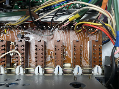
All switches on this board can be easily cleaned and lubricated during the servicing. However, the "Tape Copy" and "Tape Monitor" switches are located between this and another small board, as seen in the photo below. The small top PCB must be removed to access all hidden switches for cleaning. This can be a challenging task for those who don't have the right tools. For this purpose, I used my Hakko FR301 desoldering tool, which greatly helped.
"Tape Copy" and "Tape Monitor" switches are sandwiched between two PCBs
The small top PCB and extension shaft are removed - now it is easy to clean and lubricate
Phono Amplifier Board (P400)
To service this board, the selector extension shaft must be removed.
The phono amplifier board has 6 low leakage electrolytic capacitors (C401, C402, C409, C410, C417, C418) and 2 aluminum e-caps (C423, C424). All original low leakage e-caps were replaced with modern low leakage Nichicon UKL caps. The remaining aluminum e-caps were replaced with ow impedance Nichicon UPW caps.
Test results on original capacitors removed from the phono amplifier board:
C401: rated capacitance – 4.7uF, measured – 4.4uF, ESR – 2.1Ω, deviation: -6%
C402: rated capacitance – 4.7uF, measured – 4.8uF, ESR – 1.8Ω, deviation: +2%
C409: rated capacitance – 33uF, measured – 37uF, ESR – 1.57Ω, deviation: +12%
C410: rated capacitance – 33uF, measured – 37uF, ESR – 1.43Ω, deviation: +12%
C417: rated capacitance – 4.7uF, measured – 4.3uF, ESR – 2.2Ω, deviation: -9%
C418: rated capacitance – 4.7uF, measured – 4.2uF, ESR – 2.9Ω, deviation: -11%
C423: rated capacitance – 47uF, measured – 48uF, ESR – 0.21Ω, deviation: +2%
C424: rated capacitance – 47uF, measured – 48uF, ESR – 0.18Ω, deviation: +2%
The first stage of the phono amplifier circuit is a differential amplifier consisting of two amplifying transistors with a common emitter: Q401/Q403 (left channel) and Q402/Q404 (right channel). The original PNP transistors installed in these positions are 2SA872. These transistors are not on my list of infamous transistors that are prone to failure. But I decided to test them anyway to check how well they matched.
Testing showed that the transistors installed in the left channel are poorly matched in terms of DC current gain. The mismatch between these transistors was ~21% which is pretty substantial for transistors installed in the differential amplifier. The mismatch between two transistors installed in the right channel was ~9%.
So, I replaced each pair of original 2SA872 transistors with new close-matched pair of modern low-noise Fairchild KSA992s to improve the performance and reliability of the differential amplifier. The replacement transistor has the same pinout as the original one.
Test results on original 2SA872 transistors
Q401 (left channel): hfe - 372, Vbe - 0.778V
Q403 (left channel): hfe - 307, Vbe - 0.779V
Q402 (right channel): hfe - 356, Vbe - 0.778V
Q404 (right channel): hfe - 327, Vbe - 0.777V
Test results on new KSA992 transistors
Q401 (left channel): hfe - 404, Vbe - 0.761V
Q403 (left channel): hfe - 409, Vbe - 0.759V
Q402 (right channel): hfe - 408, Vbe - 0.760V
Q404 (right channel): hfe - 410, Vbe - 0.761V
Phono amplifier board - before and after
Dial and Meter Lamps
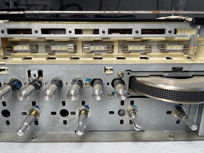
The easiest way to replace the dial lamps in Marantz 2285B is to disassemble the PCB holding these lamps from the plastic holder. It was probably possible to do about 20 or 30 years ago when the plastic holder was more flexible. Now, this unit is almost 45 years old, and any attempts to do it will certainly result in the breakage of the small plastic tabs. Because of that, I always prefer to replace the old incandescent lamps from the front. I have described this procedure many times in my previous posts (see for more details here).
The old incandescent lamps were replaced with warm white LED lamps to maintain the original look and decrease heat. The original incandescent lamps behind two meters were also replaced with warm white LED lamps. Note, that there is no vellum paper behind the dial scale in Marantz 2285B (European version).
Dial scale removed - original incandescent dial lamps
Dial scale removed - warm white LED lamps
DC offset and Bias Adjustments
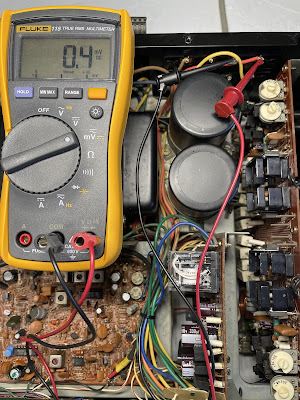
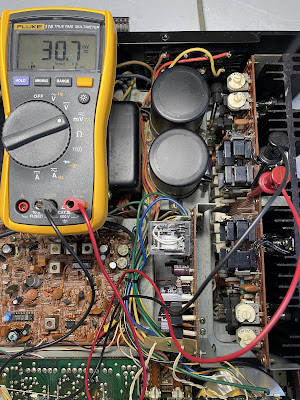
The DC offset is measured across speaker terminals on each channel. It should be adjusted as close to zero volts as possible with the trimming resistors R726 and R776, respectively.
The bias is measured across two emitter resistors (R743 and R744) on the left channel, and across two emitter resistors (R793 and R794) on the right channel. It should be adjusted to ~30mV with trimming resistors R727 and R777, respectively. It corresponds to the idling current of 20mA.
DC offset on the left and right channels after restoration
Bias on the left and right channels after restoration
Output Power Test
The final output power test was performed at the end of my restoration. The receiver was loaded with a low inductance 8Ω/100W dummy resistor for each channel. The oscilloscope was connected across the speaker terminals and a sine-wave signal of 1kHz was applied to the AUX jacks. The output sine-wave signal was perfectly symmetrical on both channels with no clipping up to 26.73 VRMS (left channel) and 25.98 VRMS (right channel). It corresponds to the output power of 89.3W on the left channel and 84.4W on the right channel.
Output power test
As usual, all the knobs and the face plate were gently cleaned in warm water with dish soap. All controls have been cleaned with DeoxIT 5% contact cleaner and lubricated with DeoxIT FaderLube 5% spray.
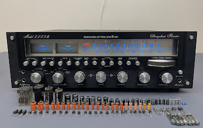
The final result can be seen in the photos below. This classic Marantz receiver looks and sounds magnificent. It is a real "black pearl" for any Marantz lovers. Please watch a short demo video at the end of this post. Thank you for reading.
Marantz 2285B - after restoration

_removed%20from%20the%20chassis.jpg)

_before%20servicing.jpg)
_after%20servicing.jpg)


_before%20servicing.jpg)
_after%20servicing.jpg)
_before%20servicing.jpg)
_after%20servicing.jpg)
_before%20servicing.jpg)
_after%20servicing.jpg)

_before%20servicing.jpg)
_after%20servicing.jpg)





Beautiful well done !
ReplyDeleteFantastic restoration and repair back to life.
ReplyDeleteHi Oleg, just FYI I am restoring a black Euro 2285B and it did come with a 10uF/50V C804.
ReplyDeleteThanks for sharing!
Delete