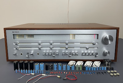
Unit: FM Stereo Receiver
Manufacturer: Yamaha
Model: CR-1000
SN: 6394
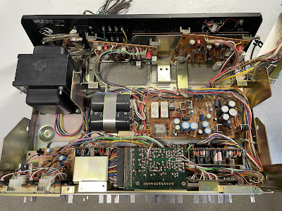
Today I'm showcasing a Yamaha CR-1000 natural sound FM stereo receiver that came in for restoration. This model was introduced in 1974 and produces 70 watts per channel into 8 ohms with less than 0.1% total harmonic distortion. The damping factor is 70.
As far as I know, the Yamaha CR-1000 had a limited distribution and was initially sold only in Japan as a high-end model for 180,000¥. The US list price was $799.95 (Ref. High Fidelity Magazine, June 1974, page 50). It is a forerunner of the famous CR-1020, CR-2020, and CR3020 AM/FM stereo receivers introduced to the market a few years later. The CR-1000 was a milestone. As the Yamaha sales brochure states the CR-1000 is a combination of an outstanding FM tuner and an extremely low-distortion, high-power, versatile amplifier, both of which could stand by themselves as independent Hi-Fi components. The unit features the world's first application of negative feedback to the FM tuner's multiplex switching circuit, resulting in very low harmonic distortion and intermodulation distortion. Because the FM tuner uses an elaborate 5-gang tuning capacitor, as well as a triple tuning circuit with dual-gated MOSFET's, the quality of FM reception is at the highest level presently possible for a tuner of any cost.
The direct-coupled OCL power amplifier itself allows negative feedback to be applied evenly from DC to far above the audio spectrum while reducing distortion and expanding the power bandwidth to 5 - 50,000Hz with a total harmonic distortion of 0.5%. It also extends the damping factor and output characteristics through the very low frequencies, contributing excellent transient response capabilities in the low-frequency range.
That being said, the Yamaha CR-1000 is not a service-friendly receiver, and you'll soon see why.
Main Amplifier Board (NA06599)
The main amplifier board has two bi-polar capacitors (C601, C603) and one aluminum e-cap (C609). The bi-polar capacitor C601 installed in the input signal path was replaced with a high-quality film polyester WIMA cap. Another bi-polar capacitor C603 was replaced with a new bi-polar Nichicon UES cap. The remaining aluminum e-cap C609 was replaced with a low impedance Nichicon UPW cap.
Test results on original capacitors removed from the main board:
Left channel:
C601: rated capacitance – 2.2uF, measured – 2.1uF, ESR – 1.48Ω, deviation: -5%
C603: rated capacitance – 47uF, measured – 52uF, ESR – 0.08Ω, deviation: +11%
C609: rated capacitance – 220uF, measured – 241uF, ESR – 0.12Ω, deviation: +10%
Right channel:
C601: rated capacitance – 2.2uF, measured – 2.1uF, ESR – 2.7Ω, deviation: -5%
C603: rated capacitance – 47uF, measured – 53uF, ESR – 0.07Ω, deviation: +13%
C609: rated capacitance – 220uF, measured – 243uF, ESR – 0.11Ω, deviation: +11%
All original trimming resistors (VR601, VR602, VR603) were replaced with new Bourns potentiometers.
Main amplifier board (left and right channel) - before and after
Power Supply Board (NA06598)
The power supply board in almost any vintage gear is fairly easy to access and service. But this is not the case with Yamaha CR-1000. This is where the troubles begin. You need to remove the tuner unit to access the power supply board. No, I am not kidding. This "smart" engineering solution is designed to worsen the life of a technician. In fact, the tuner unit must be removed to access any of the printed circuit boards, except for the two main amplifier boards. Did I tell you that I'm not a big fan of Yamaha vintage gears? Anyway, let's get back to work.
Remove the four red-topped 3x8S bind tapping screws, two large slot screws, and the red-topped screws. Then remove the tuner unit. That's what it says in the service manual. Will the tuner unit be completely disconnected from the rest of the chassis to make the servicing easy? No! It will be still connected to the other boards. And you should be extremely careful not to pull too hard on the leads when removing the tuner unit. Otherwise, some leads or wires can be broken. So, think twice if you want to service this receiver yourself.
Yamaha CR-1000 - the tuner unit is removed (but still connected to other boards!)
The power supply board has sixteen aluminum electrolytic capacitors (C802, C803, C804, C805, C806, C808, C810, C811, C812, C813, C814, C815, C817, C818, C822, C823) and two bi-polar e-caps (C819, C820). All aluminum e-caps (except the e-cap C808) were replaced with low impedance Nichicon UPW/UPM/UHE caps. The aluminum e-cap C808 and bi-polar e-cap C820 were replaced with high-quality film polyester WIMA caps. And the remaining bi-polar e-cap C820 was replaced with a new bi-polar Nichicon UEP cap.
Test results on original capacitors removed from the power supply board:
C802: rated capacitance – 220uF, measured – 233uF, ESR – 0.04Ω, deviation: +6%
C803: rated capacitance – 220uF, measured – 246uF, ESR – 0.04Ω, deviation: +12%
C804: rated capacitance – 220uF, measured – 228uF, ESR – 0.02Ω, deviation: +4%
C805: rated capacitance – 220uF, measured – 241uF, ESR – 0.01Ω, deviation: +10%
C806: rated capacitance – 10uF, measured – 13uF, ESR – 0.72Ω, deviation: +30%
C808: rated capacitance – 1uF, measured – 1.3uF, ESR – 2.5Ω, deviation: +30%
C810: rated capacitance – 470uF, measured – 604uF, ESR – 0.09Ω, deviation: +29%
C811: rated capacitance – 220uF, measured – 277uF, ESR – 0.14Ω, deviation: +26%
C812: rated capacitance – 220uF, measured – 264uF, ESR – 0.14Ω, deviation: +20%
C813: rated capacitance – 470uF, measured – 596uF, ESR – 0.08Ω, deviation: +27%
C814: rated capacitance – 220uF, measured – 274uF, ESR – 0.13Ω, deviation: +25%
C815: rated capacitance – 33uF, measured – 33uF, ESR – 0.68Ω, deviation: 0%
C817: rated capacitance – 47uF, measured – 44uF, ESR – 0.12Ω, deviation: -6%
C818: rated capacitance – 47uF, measured – 52uF, ESR – 0.11Ω, deviation: +11%
C819: rated capacitance – 100uF, measured – 114uF, ESR – 0.21Ω, deviation: +14%
C820: rated capacitance – 1uF, measured – 1uF, ESR – 0.61Ω, deviation: 0%
C822: rated capacitance – 10uF, measured – 12uF, ESR – 2.1Ω, deviation: +20%
C823: rated capacitance – 4.7uF, measured – 6.1uF, ESR – 0.55Ω, deviation: +30%
The original speaker protection relay (HC2-P-DC12V) was replaced with a new Omron MY2-02-DC12 relay. The original relay was still functional but I replaced it anyway. Recently, I started to replace the protection relay in all vintage gears even if they are still functional. It is now a part of preventive maintenance. Even the protection relay still works fine, the relay contacts usually toasted, and no one knows how long it will last. The toasted contacts are poor conductors and often result in intermittent distortion in either the left or right channel.
The four NPN transistors (TR806, TR813, TR815, and TR816) installed on this board are 2SC458 transistors that are prone to failure. I replaced them with new Fairchild KSC1845 transistors. Watch the pinout on replacement transistors. The original transistor is BCE and the new one is ECB.
Power supply board - before and after
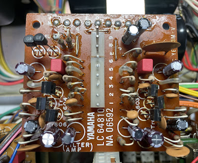
Filter Amplifier Board (NA06592)
Reminder: first of all, remove the tuner unit. Again, this is not a joke.
The filter amplifier board has six solid tantalum capacitors (C601, C602, C603, C604, C619, C620) installed in the signal path, and six aluminum electrolytic capacitors (C605, C606, C609, C610, C617, C618). Two tantalum capacitors C603 and C604 were replaced with high-quality film polyester WIMA caps. The other four tantalum caps were replaced with modern low leakage Nichicon UKL caps. And the remaining aluminum e-caps were replaced with low impedance Nichicon UPW caps.
Test results on original capacitors removed from the filter amplifier board:
C601: rated capacitance – 2.2uF, measured – 2.2uF, ESR – 0.52Ω, deviation: 0%
C602: rated capacitance – 2.2uF, measured – 2.2uF, ESR – 0.72Ω, deviation: 0%
C603: rated capacitance – 1uF, measured – 1.0uF, ESR – 3.7Ω, deviation: 0%
C604: rated capacitance – 1uF, measured – 1.1uF, ESR – 2.2Ω, deviation: +10%
C605: rated capacitance – 10uF, measured – 13uF, ESR – 1.41Ω, deviation: +30%
C606: rated capacitance – 10uF, measured – 12uF, ESR – 1.61Ω, deviation: +20%
C609: rated capacitance – 10uF, measured – 13uF, ESR – 1.38Ω, deviation: +30%
C610: rated capacitance – 10uF, measured – 12uF, ESR – 1.49Ω, deviation: +20%
C617: rated capacitance – 100uF, measured – 125uF, ESR – 1.44Ω, deviation: +25%
C618: rated capacitance – 100uF, measured – 130uF, ESR – 0.37Ω, deviation: +30%
C619: rated capacitance – 2.2uF, measured – 2.2uF, ESR – 1.26Ω, deviation: 0%
C620: rated capacitance – 2.2uF, measured – 2.1uF, ESR – 1.61Ω, deviation: -5%
Filter amplifier board - before and after
Mic Amplifier Board (NA06591)
First of all, remove the tuner unit.
The Mic amplifier board has three solid tantalum capacitors (C652, C654, C655) installed in the signal path, and three aluminum electrolytic capacitors (C651, C659, C663). I replaced the tantalum capacitors with film polyester WIMA caps. And the remaining aluminum e-caps were replaced with low impedance Nichicon UPW caps.
Test results on original capacitors removed from the mic amplifier board:
C651: rated capacitance – 47uF, measured – 51uF, ESR – 0.32Ω, deviation: +9%
C652: rated capacitance – 1uF, measured – 1.1uF, ESR – 3.4Ω, deviation: +10%
C654: rated capacitance – 1uF, measured – 1.1uF, ESR – 5.6Ω, deviation: +10%
C655: rated capacitance – 1uF, measured – 1.1uF, ESR – 6.5Ω, deviation: +10%
C659: rated capacitance – 100uF, measured – 131uF, ESR – 2.1Ω, deviation: +31%
C663: rated capacitance – 4.7uF, measured – 5.3uF, ESR – 1.58Ω, deviation: +13%
Mic amplifier board - before and after
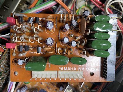
Tone Control Amplifier (NA06593)
First of all, remove the tuner unit.
The tone control amplifier board has six solid tantalum capacitors (C471, C472, C485, C486, C487, C488) installed in the signal path, and four aluminum electrolytic capacitors (C479, C480, C481, C482). Two tantalum capacitors C471 and C472 were replaced with film polyester WIMA caps. The other four tantalum caps were replaced with modern low leakage Nichicon UKL capacitors. And the remaining aluminum e-caps were replaced with low impedance Nichicon UPW caps.
Test results on original capacitors removed from the tone control amplifier board:
C471: rated capacitance – 1uF, measured – 1.1uF, ESR – 3.8Ω, deviation: +10%
C472: rated capacitance – 1uF, measured – 1.1uF, ESR – 0.9Ω, deviation: +10%
C479: rated capacitance – 100uF, measured – 120uF, ESR – 0.35Ω, deviation:+20 %
C480: rated capacitance – 100uF, measured – 123uF, ESR – 0.34Ω, deviation: +23%
C481: rated capacitance – 10uF, measured – 13uF, ESR – 2.21Ω, deviation: +30%
C482: rated capacitance – 10uF, measured – 13uF, ESR – 1.54Ω, deviation: +30%
C485: rated capacitance – 3.3uF, measured – 3.4uF, ESR – 1.11Ω, deviation: +3%
C486: rated capacitance – 3.3uF, measured – 3.3uF, ESR – 1.57Ω, deviation: 0%
C487: rated capacitance – 33uF, measured – 36uF, ESR – 2.3Ω, deviation: +9%
C488: rated capacitance – 33uF, measured – 34uF, ESR – 0.36Ω, deviation: +3%
Tone control amplifier - before and after
Equalizer Amplifier Board (NA06594)
First of all, remove the tuner unit.
The equalizer amplifier board has eight solid tantalum capacitors (C401, C402, C415, C416, C427, C428, C429, C430) installed in the signal path, and three aluminum electrolytic capacitors (C413, C414, C431). Four tantalum capacitors (C401, C402, C415, C416) were replaced with film polyester WIMA caps. Note, that the original e-cap C402 has a very high ESR value. The other four tantalum caps were replaced with modern low leakage Nichicon UKL capacitors. And the remaining aluminum e-caps were replaced with low impedance Nichicon UPW caps.
Test results on original capacitors removed from the equalizer amplifier board:
C401: rated capacitance – 1uF, measured – 1.0uF, ESR – 5.1Ω, deviation: 0%
C402: rated capacitance – 1uF, measured – 1.0uF, ESR – 14.1Ω, deviation: 0%
C413: rated capacitance – 33uF, measured – 34uF, ESR – 0.76Ω, deviation: +3%
C414: rated capacitance – 33uF, measured – 35uF, ESR – 0.85Ω, deviation: +6%
C415: rated capacitance – 1uF, measured – 1.1uF, ESR – 1.22Ω, deviation: +10%
C416: rated capacitance – 1uF, measured – 1.1uF, ESR – 1.23Ω, deviation: +10%
C427: rated capacitance – 4.7uF, measured – 4.8uF, ESR – 1.16Ω, deviation: +2%
C428: rated capacitance – 4.7uF, measured – 4.8uF, ESR – 0.88Ω, deviation: +2%
C429: rated capacitance – 4.7uF, measured – 4.8uF, ESR – 0.96Ω, deviation: +2%
C430: rated capacitance – 4.7uF, measured – 4.9uF, ESR – 1.38Ω, deviation: +4%
C431: rated capacitance – 47uF, measured – 51uF, ESR – 0.81Ω, deviation: +9%
Equalizer amplifier board - before and after
Power Transistors
The original Sanken's power transistors (2SC1116 x 2, 2SA747 x 2) were removed, cleaned, and tested with Atlas DCA55 semiconductor analyzer. The measured DC current gain on three out of four transistors was in spec. But the NPN transistor (2SC1116) from the right channel has a relatively low gain. I decided to replace all four power transistors with new ON Semiconductor MJ21193G/MJ21194G transistors. The new transistors are specifically designed for high-power audio output and have excellent gain linearity. So, it is a perfect choice as substitution transistors for the original Sanken's power transistors.
Below are the test results on the original and new power transistors. It should be noted that Atlas DCA55 semiconductor analyzer provides the accurate reading for DC current gain only on low power transistors. A high-power transistor requires a much higher collector current and collector-emitter voltage to accurately measure its current gain. However, it is still a very useful device for comparing transistors of a similar type for the purposes of gain matching or fault-finding.
Test results on original power transistors
TR611 (left channel, 2SC1116): gain - 65, Vbe - 0.592V
TR612 (left channel, 2SA747): gain - 118, Vbe - 0.614V
TR611 (right channel, 2SC1116): gain - 26, Vbe - 0.583V
TR612 (right channel, 2SA747): gain - 77, Vbe - 0.603V
Test results on new ON Semiconductor power transistors
TR611 (left channel, MJ21194G): gain - 62, Vbe - 0.596V
TR612 (left channel, MJ21193G): gain - 86, Vbe - 0.605V
Meter Lamps
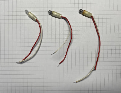
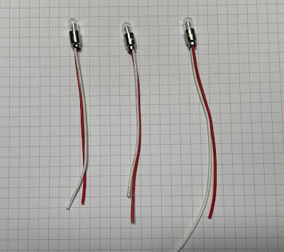
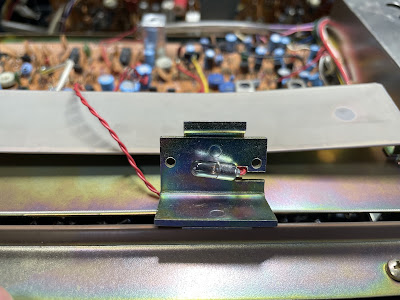
Two of the three original meter lamps were burned out in this unit. I replaced them with new incandescent lamps. This is perhaps the easiest part while servicing the Yamaha CR-1000. But you must first remove the tuner unit to unsolder the lamp wires from the PCB (sad but true).
Meter lamps - original, removed from the lamp holders
Original and new meter lamps
Meter lamps - new lamps are installed
Dial Pointer Lamp
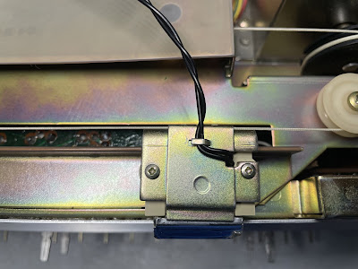
There is no backlit to the dial scale in CR-1000 but the dial pointer is illuminated (similar to the Yamaha CR-1020). And unlike many other vintage receivers, it's relatively easy to replace the burned pointer bulb on this model. One just needs to unscrew two small screws on the top of the dial pointer unit and the lamp will be released.
Original dial pointer lamp - disassembled from the holder
Filter Capacitors
Two filter capacitors are located under the tuner unit (sorry about that). I tested them with Atlas ESR70 capacitance meter (in-circuit test). Both caps are still within the factory capacitance tolerance and have almost zero ESR. So, I didn't change them. In general, the filter capacitors rarely fail in vintage gears, and I usually don't replace them unless their ESR is high.
In-circuit test on two filter capacitors - both are still in spec
Filter cap #1: rated capacitance – 10000uF, measured – 9365uF, ESR – 0.02Ω, deviation: -6%
Filter cap #2: rated capacitance – 10000uF, measured – 9409uF, ESR – 0.01Ω, deviation: -6%
Main Amplifier Adjustments
Three adjustments should be done to each main amplifier board: (i) primary stage differential amplification circuit current, (ii) mid-point voltage (or DC offset), and (iii) idling current (or Bias). All three steps are clearly described in the service manual.
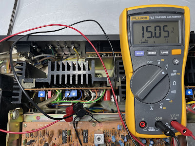
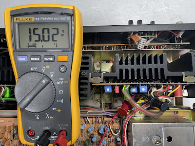
(i) The DC voltmeter should be connected between terminals TP1 (-) and TP2 (+). The voltage should be adjusted to 15V +/- 0.15V with the trimming resistor VR602.
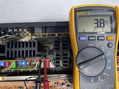
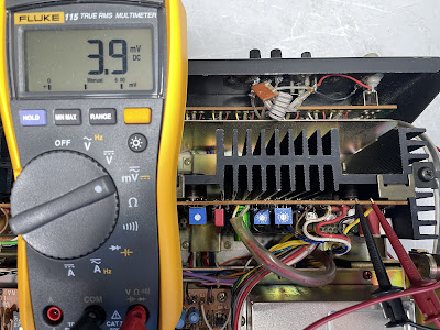
(ii) The DC voltmeter should be connected between terminals OUT and E. The voltage should be adjusted to 0V +/- 10mV with the trimming resistor VR601.
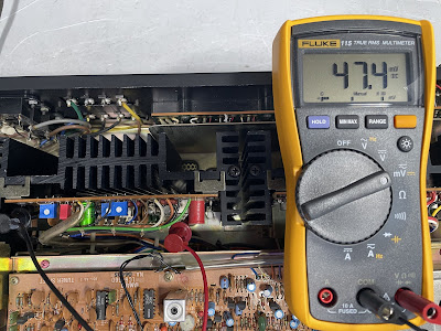
(iii) The DC voltmeter should be connected between terminals TP3 (+) and TP4 (-). The voltage should be adjusted to 47mV +/- 10mV.
Primary stage differential amplification circuit current on the left and right channels after restoration
Mid-point voltage (or DC offset) on the left and right channels after restoration
Idling current (or Bias) on the left and right channels after restoration
Output Power Test
The final output power test was performed at the end of my restoration. The receiver was loaded with a low inductance 8Ω/100W dummy resistor for each channel. The oscilloscope was connected across the speaker terminals and a sine-wave signal of 1kHz was applied to the AUX jacks. The output sine-wave signal was perfectly symmetrical on both channels with no clipping up to 26.41 VRMS (left channel) and 26.07 VRMS (right channel). It corresponds to the output power of 87.2W on the left channel and 85.0W on the right channel.
Output power test
As usual, all the knobs and the front panel were gently cleaned in warm water with dish soap. All controls have been cleaned with DeoxIT 5% contact cleaner and lubricated with DeoxIT FaderLube 5% spray (I recommend doing it while servicing all boards located under the tuner unit. Otherwise, the tuner unit should be disassembled again to reach most switches and sliders). The wood case was treated with Howard's Restor-A-Finish.
The final result can be seen in the photos below. The receiver looks great, works properly, and sounds awesome. Please watch a short demo video at the end of this post. Thank you for reading.
Yamaha CR-1000 - after restoration
Demo video after repair & restoration


