Unit: AM/FM Stereo Receiver
Manufacturer: Fisher
Model: 201
SN: 73398
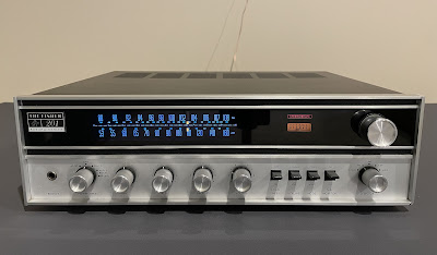
Another classic stereo receiver made by Fisher Corp came on my bench for restoration. The Fisher 201 "Futura Series" was introduced in 1972 and produces 20 watts per channel into 8 ohms with less than 1% total harmonic distortion. The optional walnut veneer cabinet for this model is 21-UW. The list price in 1972 was $249.95 (Ref. High Fidelity Magazine, April 1972).
Power Supply Board
The power supply board provides +15.5V DC for the tuner section, +31.5V DC for the pre-amplifier and control amplifier, and +53V DC for the power amplifier. This board has three aluminum electrolytic capacitors: C01, C02, and C03. I replaced them with low-impedance Nichicon UPW caps. The original e-caps were tested with an Atlas ESR70 capacitance meter and the results are below. All original capacitors still have very low ESR, but the capacitance tolerance is outside the factory specification.
Test results on original capacitors removed from the power supply board:
C01: rated capacitance – 47uF, measured – 57uF, ESR – 0.11Ω, deviation: +21%
C02: rated capacitance – 47uF, measured – 61uF, ESR – 0.08Ω, deviation: +30%
C03: rated capacitance – 100uF, measured – 131uF, ESR – 0.14Ω, deviation: +31%
The regulating transistor Q01 mounted on the heat sink is a 2SC1226 transistor. In my experience with restoring Fisher 201/202 receivers, the intermittent or unstable operation of the tuner section is often caused by the aging of this transistor. I replaced it with a new Fairchild MJE15032G transistor.
Power supply board - before and after
Power Amplifier Board
Similar to the Fisher 202, each channel in the Fisher 201 has a separate driver board inserted vertically into the slot. This makes the servicing of these boards very easy.
Each driver board has four aluminum electrolytic capacitors: C01, C02, C03, and C04. I replaced the e-cap C01 installed in the signal path with a high-quality film polyester WIMA cap. The remaining aluminum capacitors were replaced with low-impedance Nichicon UPW caps.
Test results on original capacitors removed from the power amplifier boards:
Left channel:
C01: rated capacitance – 1uF, measured – 1.6uF, ESR – 5.2Ω, deviation: +60%
C02: rated capacitance – 47uF, measured – 48uF, ESR – 0.42Ω, deviation: +2%
C03: rated capacitance – 100uF, measured – 141uF, ESR – 0.74Ω, deviation: +41%
C04: rated capacitance – 47uF, measured – 69uF, ESR – 0.18Ω, deviation: +47%
Right channel:
C01: rated capacitance – 1uF, measured – 1.8uF, ESR – 4.4Ω, deviation: +80%
C02: rated capacitance – 47uF, measured – 59uF, ESR – 0.22Ω, deviation: +26%
C03: rated capacitance – 100uF, measured – 142uF, ESR – 0.62Ω, deviation: +42%
C04: rated capacitance – 47uF, measured – 66uF, ESR – 0.87Ω, deviation: +40%
The capacitance tolerance of all original capacitors (except C02 from the left channel) is outside the factory specifications.
Driver boards - before and after
Power Transistors
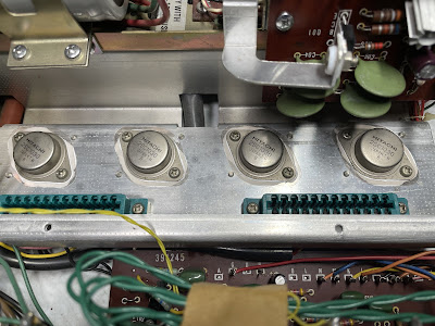
The original Hitachi 2SC1030 power transistors were removed, cleaned, and tested with Atlas DCA55 semiconductor analyzer. The measured DC current gain on all transistors met the specifications in the datasheet. Each pair of transistors was also very well matched within ~4%. Not too bad for 50+ old vintage gear! I mounted all the transistors back on the heat sink and applied fresh thermal paste. The old thermal pads were also replaced with new Mica ones.
Original power transistors with new Mica pads and fresh thermal paste
Pre-Amplifier Board
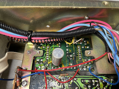
The pre-amplifier board has seven aluminum electrolytic capacitors: C01, C02, C11, C12, C13, C14, and C19. Four of them (C01, C02, C13, C14) are installed in the signal path. I replaced these capacitors with modern low-leakage Nichicon UKL caps to improve the signal-to-noise ratio. The remaining capacitors were replaced with low-impedance Nichicon UPW caps. Note that the filtering e-cap C19 is soldered on the foil side of the PCB.
Test results on original capacitors removed from the pre-amplifier board:
C01: rated capacitance – 10uF, measured – 17uF, ESR – 1.73Ω, deviation: +70%
C02: rated capacitance – 10uF, measured – 16uF, ESR – 2.41Ω, deviation: +60%
C11: rated capacitance – 100uF, measured – 149uF, ESR – 0.44Ω, deviation: +49%
C12: rated capacitance – 100uF, measured – 145uF, ESR – 0.52Ω, deviation: +45%
C13: rated capacitance – 10uF, measured – 15uF, ESR – 0.78Ω, deviation: +50%
C14: rated capacitance – 10uF, measured – 16uF, ESR – 0.74Ω, deviation: +60%
C19: rated capacitance – 47uF, measured – 74uF, ESR – 0.33Ω, deviation: +57%
Again, the capacitance tolerance of all original capacitors from this board is outside the factory specifications.
Filtering e-cap C19 is soldered on the foil side of the PCB
Pre-amplifier board - before and after
Control Amplifier Board
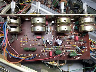
The control amplifier board has nine aluminum electrolytic capacitors: C503, C504, C511, C512, C513, C514, C517, C518, and C525. The e-caps installed in the signal path (C513, C514, C517, and C518) were replaced with film polyester WIMA caps. The other four e-caps installed in the signal path (C503, C504, C511, and C512) were replaced with modern low-leakage Nichicon UKL caps. And the remaining filtering capacitor C525 was replaced with a low-impedance Nichicon UPW cap.
Test results on original capacitors removed from the control amplifier board:
C503: rated capacitance – 10uF, measured – 15uF, ESR – 3.1Ω, deviation: +50%
C504: rated capacitance – 10uF, measured – 15uF, ESR – 3.0Ω, deviation: +50%
C511: rated capacitance – 4.7uF, measured – 9.6uF, ESR – 5.2Ω, deviation: +104%
C512: rated capacitance – 4.7uF, measured – 9.7uF, ESR – 2.2Ω, deviation: +106%
C513: rated capacitance – 1uF, measured – 1.3uF, ESR – 4.1Ω, deviation: ++30%
C514: rated capacitance – 1uF, measured – 1.4uF, ESR – 3.7Ω, deviation: +40%
C517: rated capacitance – 1uF, measured – 1.4uF, ESR – 3.6Ω, deviation: +40%
C518: rated capacitance – 1uF, measured – 1.3uF, ESR – 4.1Ω, deviation: +30%
C525: rated capacitance – 220uF, measured – 311uF, ESR – 0.05Ω, deviation: +41%
As expected, the capacitance tolerance of all original capacitors from this board is outside the factory specifications. The measured capacitance of the two e-caps (C511 & C512) is almost double their nominal capacitance! Yeah, everything ages and electronic components are no exception.
The 2SC458 NPN transistors installed on this board are prone to failure. A typical failure mode of 2SC458 is noise and/or static. I replaced every 2SC458 transistor with a modern low-noise Fairchild KSC1845. Keep an eye on the pinout of the replaced transistors when servicing this board. The original transistor is BCE and the new one is ECB.
All controls on this board were cleaned and lubricated with DeoxIT FaderLube 5% spray.
Control amplifier board - before and after
Dial, Meter, and Stereo Indicator Lamps
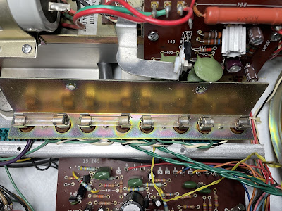
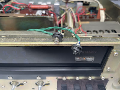
To replace the dial lamps in Fisher 201 just unscrew two small screws on the top of the dial scale. Then slide the dial lamp bracket to the rear and drop the bracket to get to the lamps. I replaced the original incandescent bulbs with warm white LED lamps to maintain the original look and decrease heat.
Old incandescent dial lamps
New warm white LED lamps
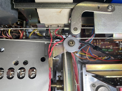
The meter and stereo indicator lamps in this receiver burned out. I replaced them with new incandescent lamps.
Two original meter lamps
New meter lamps are installed
Two original stereo indicator lamps
New stereo indicator lamps are installed
Center Voltage Test
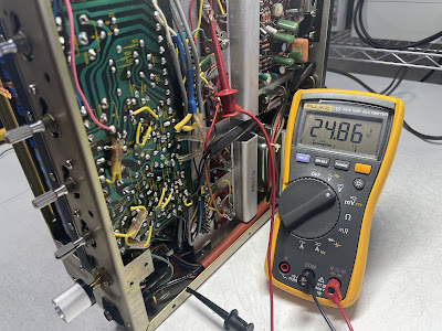
The driver boards in the Fisher 201 do not have trimmers to adjust the center voltage. The service manual simply recommends doing a center voltage test to make sure the amplifier works properly. The test is very simple. First of all, the supply voltage should be measured between pin #3 and the ground. In this unit, the measured supply voltage was ~51.8V. Then, the center voltage should be measured on each board between pin #5 and the ground. This voltage should be half of the supply voltage within +/- 2V. As can be seen from the pictures below, the measured voltage on the left and right channel driver boards were 25.12V and 24.86V, respectively. So, it is approximately half of the supply voltage within +/- 1V. The unit passed the center voltage test, and both channels work properly.
Supply voltage measured between pin #3 and the ground
Center voltage measured between pin #5 and the ground (left channel)
Center voltage measured between pin #5 and the ground (right channel)
Output Power Test
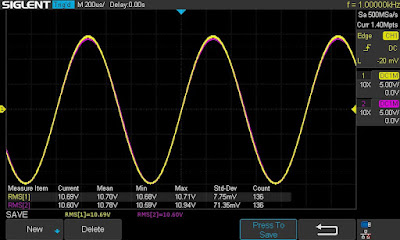
The final output power test was performed at the end of my restoration. The receiver was loaded with a low inductance 8Ω/100W dummy resistor for each channel. The oscilloscope was connected across the speaker terminals and a sine-wave signal of 1kHz was applied to the AUX jacks. The output sine-wave signal was perfectly symmetrical on both channels with no clipping up to 10.69 VRMS (left channel) and 10.60 VRMS (right channel). It corresponds to the output power of 14.3W on the left channel and 14.0W on the right channel.
Output power test
As usual, all the knobs and the front panel were gently cleaned in warm water with dish soap. All controls have been cleaned with DeoxIT 5% contact cleaner and lubricated with DeoxIT FaderLube 5% spray.










I recently picked one of these up but the meter and stereo lamps are burned out. What size lamps did you use?
ReplyDeleteI believe I used the following incandescent lamps in this model:
Deletemeter lamp: 4.7mm, 8V/60mA, x2 lamps
stereo lamp: 4mm, 6V/50mA, x2 lamps