Unit: AM/FM Stereo Receiver
Manufacturer: Realistic
Model: STA-180
SN: 07002284
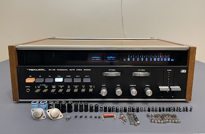
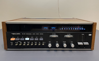
One of my customers brought in a rather rare vintage Realistic STA-180 stereo receiver for restoration. His son-in-law bought this beautiful receiver on the action and gave it to him for his birthday. The receiver is still in excellent cosmetic condition and brought back many good memories. It's definitely worth restoring.
The Realistic STA-180 has many unique features. There is a separate front end, two dial scales, and two thumbwheel knobs (similar to Marantz's "Gyro-Touch-Tuning") for AM and FM. The variable FM muting control allows you to select a muting level for tuning weak or stronger stations (pretty unique!). The FM dial pointer changes its color to indicate a stereo reception (a very cool feature but PITA to replace burned lamps). It also has a "Flip-Top" door at the top rear allowing you to make all connections from the front of the receiver. The list price in 1972 was $399.95 (Ref. Radio Shack Catalog, 1972, ver.1, page 14).
I was not able to find a service manual for this receiver. Currently (October 2022) even the schematic is not available online. There is only one thread on AudioKarma.org about servicing this model. Also, some info is available in the 1972 Radio Shack catalog.
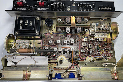
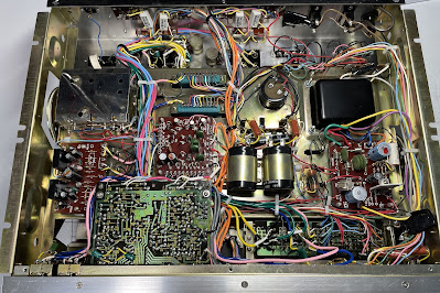
Realistic STA-180 - inside view before restoration
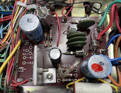
Power Supply Board
The power supply has three aluminum electrolytic capacitors: C01, C02, and C07. I replaced them with low impedance Nichicon UPW caps. The original e-caps were tested with an Atlas ESR70 capacitance meter and the results are below. Two out of three capacitors have a tolerance outside the factory specifications.
Test results on original capacitors removed from the power supply board:
C01: rated capacitance – 220uF, measured – 303uF, ESR – 0.09Ω, deviation: +38%
C02: rated capacitance – 220uF, measured – 261uF, ESR – 1.02Ω, deviation: +19%
C07: rated capacitance – 220uF, measured – 278uF, ESR – 0.46Ω, deviation: +26%
The regulating transistor TR01 installed on this board is 2SC1061. This transistor is on my list of transistors that are prone to failure and I replaced it with a new Fairchild MJE15032G. The MJE15032G is a "bulletproof" transistor and can dissipate twice the power of the original transistor: 50W vs. 25W.
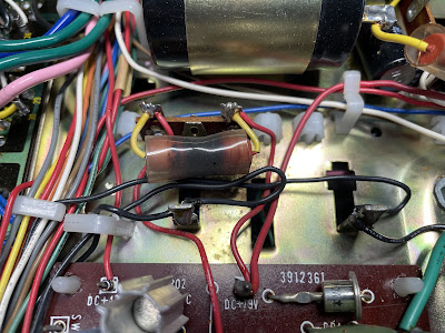
Note that the plastic sleeve of the original resistor R05 has significant discoloration. I measured the voltage drop across this resistor under normal operating conditions to calculate the current flowing through it. The voltage drop was ~46.4V. The nominal resistance of R05 is 2.2kΩ. Therefore, the current flowing through resistor R05 is 46.4V / 2.2kΩ = 21mA. And the electrical power dissipated by this resistor is 46.4V x 21mA = 0.97W. The original metal oxide resistor installed in this position has a rated power of 2W. So, it should be enough to efficiently dissipate the heat without overheating. I measured the resistance of R05 and it is still very close to the nominal. I decided to replace the original resistor with a new 3W metal oxide KOA Speer resistor as a part of "preventive maintenance".
The original (2.2kΩ/2W) and new (2.2kΩ/3W) metal oxide resistor R05
Power supply board - before and after
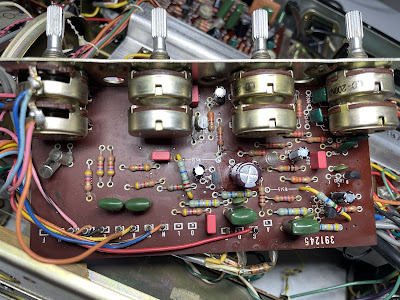
Pre-Amplifier Board
There are nineteen aluminum electrolytic capacitors on the pre-amplifier board: C03, C04, C05, C06, C11, C12, C13, C14, C15, C16, C17, C18, C31, C32, C33, C34, C37, C38, and C39. All these capacitors are ordinary aluminum electrolytic capacitors. And it's very confusing, why didn't the manufacturer install low leakage or solid tantalum capacitors in the signal path on this board? Generally, when an aluminum electrolytic capacitor is used in a coupling or decoupling circuit, only low leakage or solid tantalum capacitors are used to reduce the noise generated in the circuit. This noise depends on the leakage current of the capacitor. Less leakage current produces less noise. The typical leakage current of ordinary aluminum electrolytic capacitors is nearly 10 times higher than that of low leakage or solid tantalum capacitors. Perhaps the cost savings is the reason why low leakage or solid tantalum capacitors were not installed on this board. I don't know. In fact, none of the boards in this model (pre-amplifier, equalizer, or main amplifier) use low leakage or solid tantalum capacitors. In any case, it always makes sense to replace the capacitors in the signal path with modern low leakage or polyester film capacitors to reduce the noise generated in the circuit.
As I mentioned earlier, I was unable to find a schematic or service manual for this receiver. Thus, it was not clear which capacitors should stand in the signal path. However, an educated guess can be made that all electrolytic capacitors with a capacitance of 4.7uF or less are likely installed in the signal path. So, based on this assumption I replaced six e-caps with a capacitance of 1uF (C05, C06, C31, C32, C37, C38) with film polyester WIMA caps. The other four e-caps with a capacitance of 4.7uF (C15, C16, C33, C34) were replaced with modern low leakage Nichicon UKL caps. And the remaining nine capacitors were replaced with low impedance Nichicon UPW/UPM caps.
All controls on this board were cleaned and lubricated with DeoxIT FaderLube 5% spray.
Test results on original capacitors removed from the pre-amplifier board:
C03: rated capacitance – 10uF, measured – 17uF, ESR – 0.58Ω, deviation: +70%
C04: rated capacitance – 10uF, measured – 17uF, ESR – 0.61Ω, deviation: +70%
C05: rated capacitance – 1uF, measured – 1.7uF, ESR – 3.8Ω, deviation: +70%
C06: rated capacitance – 1uF, measured – 1.6uF, ESR – 4.3Ω, deviation: +60%
C11: rated capacitance – 10uF, measured – 17uF, ESR – 0.44Ω, deviation: +70%
C12: rated capacitance – 10uF, measured – 17uF, ESR – 0.46Ω, deviation: +70%
C13: rated capacitance – 10uF, measured – 17uF, ESR – 0.84Ω, deviation: +70%
C14: rated capacitance – 10uF, measured – 17uF, ESR – 0.46Ω, deviation: +70%
C15: rated capacitance – 4.7uF, measured – 8.9uF, ESR – 1.18Ω, deviation: +89%
C16: rated capacitance – 4.7uF, measured – 8.8uF, ESR – 1.3Ω, deviation: +87%
C17: rated capacitance – 10uF, measured – 17uF, ESR – 0.42Ω, deviation: +70%
C18: rated capacitance – 10uF, measured – 17uF, ESR – 0.52Ω, deviation: +70%
C31: rated capacitance – 1uF, measured – 1.6uF, ESR – 4.5Ω, deviation: +60%
C32: rated capacitance – 1uF, measured – 1.6uF, ESR – 4.2Ω, deviation: +60%
C33: rated capacitance – 4.7uF, measured – 8.4uF, ESR – 1.14Ω, deviation: +79%
C34: rated capacitance – 4.7uF, measured – 8.8uF, ESR – 1.2Ω, deviation: +87%
C37: rated capacitance – 1uF, measured – 1.7uF, ESR – 3.6Ω, deviation: +70%
C38: rated capacitance – 1uF, measured – 1.7uF, ESR – 3.5Ω, deviation: +70%
C39: rated capacitance – 100uF, measured – 131uF, ESR – 0.08Ω, deviation: +31%
As can be seen, all electrolytic capacitors installed on this board are out of factory tolerance spec.
The six NPN transistors (TR01 to TR06) installed on this board are the notorious 2SC458 transistors. This transistor has different types of failure modes: leakage, noise, and/or static. I replaced every 2SC458 transistor with a modern low-noise Fairchild KSC1845. Keep an eye on the pinout of the replaced transistors when servicing this board. The original transistor is BCE and the new one is ECB.
Pre-amplifier board - before and after
Main Amplifier Board
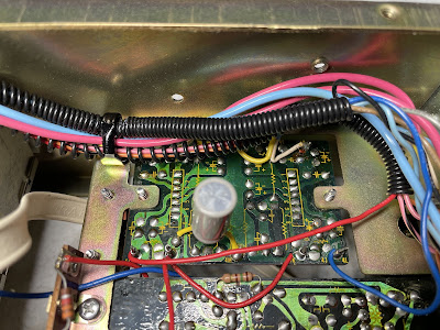
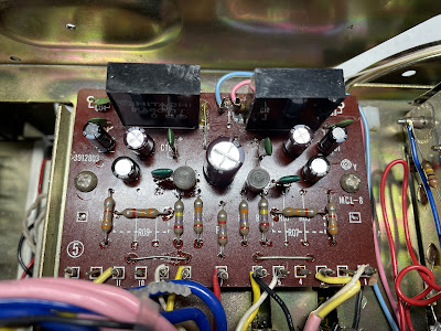
The Realistic STA-180 has two main amplifier boards. And each board is secured in the slot. This is certainly a service-friendly design.
I removed these boards from their slots and noticed that one board is marked "F" (failed?) and the other has significant discoloration around the TR04 transistor. This transistor was replaced in the past with the same type. I tested all electronic components on each board and didn't find any failed ones. Except for the electrolytic capacitors being out of factory tolerance spec, all other components are still good. So, I replaced only electrolytic capacitors on these two boards and lubricated each trimming resistor with DeoxIT FaderLube 5% spray.
Each board has four aluminum electrolytic capacitors: C01, C02, C03, and C05. The e-cap C01 is installed in the signal path. I replaced it with a high-quality film polyester WIMA cap. The remaining aluminum capacitors were replaced with low impedance Nichicon UPW/UPM caps.
Test results on original capacitors removed from the main amplifier board:
left channel:
C01: rated capacitance – 1uF, measured – 1.5uF, ESR – 5.6Ω, deviation: +50%
C02: rated capacitance – 100uF, measured – 138uF, ESR – 0.07Ω, deviation: +38%
C03: rated capacitance – 220uF, measured – 343uF, ESR – 0.21Ω, deviation: +56%
C05: rated capacitance – 47uF, measured – 61uF, ESR – 0.16Ω, deviation: +30%
right channel:
C01: rated capacitance – 1uF, measured – 1.5uF, ESR – 4.1Ω, deviation: +50%
C02: rated capacitance – 100uF, measured – 139uF, ESR – 0.08Ω, deviation: +39%
C03: rated capacitance – 220uF, measured – 434uF, ESR – 0.24Ω, deviation: +97%
C05: rated capacitance – 47uF, measured – 60uF, ESR – 0.21Ω, deviation: +28%
As expected, all electrolytic capacitors installed on this board are out of factory tolerance spec.
Main amplifier boards from the left and right channels - before restoration
Equalizer Amplifier Board
The equalizer amplifier board has seven aluminum electrolytic capacitors: C01, C02, C07, C08, C13, C14, and C17. Two of them (C01 & C02) are installed in the signal path. I replaced the C01 & C02 with modern low leakage Nichicon UKL caps to improve the signal-to-noise ratio. The remaining aluminum capacitors were replaced with low impedance Nichicon UPW caps.
Test results on original capacitors removed from the equalizer amplifier board:
C01: rated capacitance – 3.3uF, measured – 5.5uF, ESR – 3.8Ω, deviation: +67%
C02: rated capacitance – 3.3uF, measured – 5.9uF, ESR – 3.4Ω, deviation: +79%
C07: rated capacitance – 47uF, measured – 69uF, ESR – 1.2Ω, deviation: +47%
C08: rated capacitance – 47uF, measured – 69uF, ESR – 1.1Ω, deviation: +47%
C13: rated capacitance – 100uF, measured – 148uF, ESR – 0.3Ω, deviation: +48%
C14: rated capacitance – 100uF, measured – 141uF, ESR – 0.3Ω, deviation: +41%
C17: rated capacitance – 100uF, measured – 142uF, ESR – 0.1Ω, deviation: +41%
Again, all electrolytic capacitors installed on this board are out of factory tolerance spec.
Equalizer amplifier board - before and after
Power Transistors
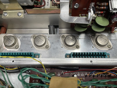
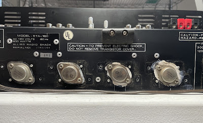
The power transistors in this unit were a mixture of the original Hitachi 2SC897 and the replacement ones 2SC1051 (see picture below). I removed all transistors and tested them with an Atlas DCA55 semiconductor analyzer. The measured DC current gain on both original Hitachi transistors met the specifications in the datasheet. But the other two transistors (2SC1051) did not pass the test since their current gain was rather low (6 and 14, respectively). So, I decided to replace these transistors with new 2SC897s from the old stock. I installed two original Hitachi 2SC897 transistors in the left channel and two new 2SC897s in the right channel.
Power transistors in this unit before servicing:
Left channel:
gain = 63 (2SC897, Hitachi)
gain = 14 (2SC1051)
Right channel:
gain = 57 (2SC897, Hitachi)
gain = 6 (2SC1051)
Power transistors in this unit after servicing:
Left channel:
gain = 63 (2SC897, Hitachi)
gain = 57 (2SC897, Hitachi)
Right channel:
gain = 67 (2SC897, Marantz)
gain = 64 (2SC897, Marantz)
FM Dial Pointer
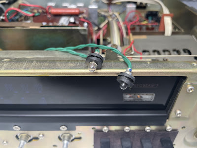
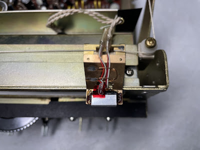
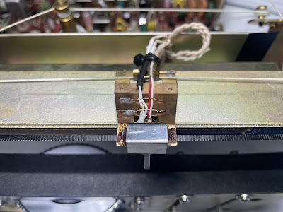
As I mentioned earlier, the FM dial pointer has a unique design. Inside the dial pointer holder are two small incandescent bulbs. One of them is wrapped in red tape. When the tuner is not tuned to a stereo station, only the bare lamp is on and the dial pointer is white. However, when stereo reception is achieved, the bare lamp dims and the "red" one lights up. The dial pointer is red. Isn't that cool? Yes! But trouble comes when one lamp burns out and needs to be replaced. The lamp wrapped in the red film was burned out in this receiver. And it took me at least a few hours to replace it. This is a rather time-consuming process since everything is very small and fragile.
FM dial pointer - two lamps inside the holder
FM dial pointer - a new lamp is installed
Dial and Meter Lamps
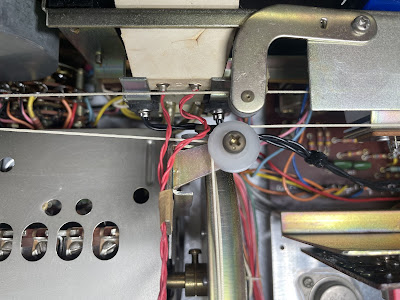
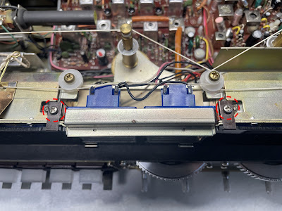
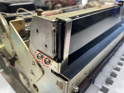
To replace the dial lamps in the STA-180, you need to remove the front panel and unscrew the two small screws on the top, and four more screws on the sides holding the small clips. Then, the dial scale can be removed from the chassis. There are eight dial lamps in total (four for AM and four for FM). I replaced the original incandescent lamps with warm white LED lamps.
Unscrew two small screws on the top, and four more screws on the sides to release the dial scale
Dial lamps - original incandescent and new warm white LED, AM and FM sections
Meter lamps can be replaced much easier. One should just unscrew two screws behind the meters and the holder can be released. I replaced the two original incandescent lamps with warm white LED lamps.
Holder for the meter lamps - just unscrew two screws and release the holder
Selector Switch Lamps
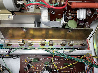
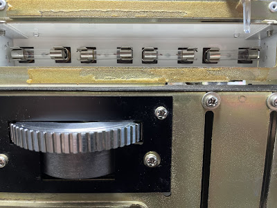
Be aware that the selector switch lamps in the Realistic STA-180 are non-standard long "fuse type" lamps rated at 10V, 0.33A. The original selector switch lamp is 43mm long while the "standard" vintage "fuse type" lamp is 30mm long. I was able to find a modern bright white LED lamps with a similar length.
Standard (30mm), non-standard (43mm), and non-standard LED (41mm) "fuse type" lamps
New LED lamps are installed
Adjustment of Idling Current and Voltage at Intermediate Point
As I mentioned earlier, no schematic or service manual for this receiver is available online (October 2022). But, the amplifier section in STA-180 has a similar design as in the integrated amplifier Hitachi IA-1000. So, I used the service manual from that amplifier as a reference.
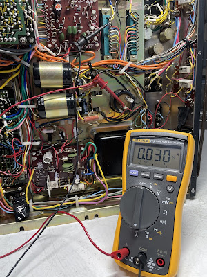
To adjust the idling current one should remove the fuse from the left (right) channel and connect the DC ammeter between the terminals of the fuse holder. I connected the DC ammeter between pin #3 and the positive terminal of the filter capacitor to measure the idling current as these are the same test points but with better access. Then the idling current was adjusted to 30mA with the trimming resistor VR02.
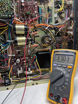
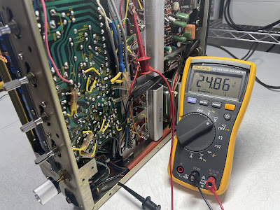
The voltage at the intermediate point can be adjusted if the DC voltmeter is connected between pin # 7 and the chassis. I adjusted it to ~37V on each channel with the trimming resistor VR01.
Idling current on the left and right channels after restoration
The voltage at the intermediate point on the left and right channels after restoration
Output Power Test
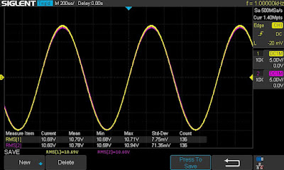
The final output power test was performed at the end of my restoration. The receiver was loaded with a low inductance 8Ω/100W dummy resistor for each channel. The oscilloscope was connected across the speaker terminals and a sine-wave signal of 1kHz was applied to the AUX jacks. The output sine-wave signal was perfectly symmetrical on both channels with no clipping up to 17.03 VRMS (left channel) and 17.07 VRMS (right channel). It corresponds to the output power of 36.3W on the left channel and 36.4W on the right channel.
Output power test
As usual, all the knobs and the front panel were gently cleaned in warm water with dish soap. All controls have been cleaned with DeoxIT 5% contact cleaner and lubricated with DeoxIT FaderLube 5% spray.
The final result can be seen in the photos below. The receiver looks pretty cool and sounds awesome! Please watch a short demo video at the end of this post. Thank you for reading.
Realistic STA-180 - after restoration









,%20and%20non-standard%20LED%20(41mm)%20fuse%20type%20lamps.jpg)


