Unit: AM/FM Stereo Receiver
Manufacturer: Marantz
Model: 2215B
SN: U160079
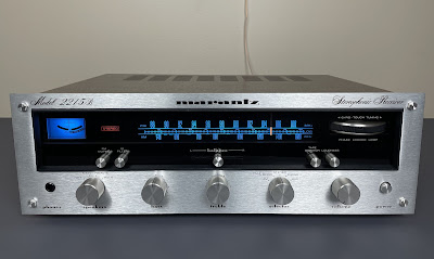
Today I'm showcasing a Marantz 2215B vintage receiver that came in for restoration. This model was manufactured from 1973 to 1977. It produces 15 watts per channel into 8 ohms with no more than 0.8% total harmonic distortion. The optional walnut veneer cabinet for this model is WC-116 or WC-15T.
Marantz 2215B is a service-friendly receiver because of very good access to each PCB. According to the factory stamp on the chassis, this unit was manufactured in May 1976.
Power Supply Board (P800)
The power supply board has six aluminum electrolytic capacitors: C804, C805, C806, C807, C808, and C810. I replaced all capacitors with low impedance Nichicon UPW/UPM caps. I found an error in the schematic regarding the e-cap C808. On the schematic and in the parts list, this capacitor is listed as 220uF/50V, even though the original capacitor installed on the board is 100uF/50V. I looked at the power supply board in another Marantz 2215B (manufactured in November 1976) that still sits on the shelf and patiently awaits restoration. The e-cap C808 installed in another 2215B is also rated for 100uF/50V. Both receivers have never been serviced. So, I replaced this e-cap with a Nichicon UPM (100uF/50V) capacitor.
The large filter capacitor C803 (3300uF/55V) is also installed on this board. It was replaced with a Nichicon LLS snap-in terminal cap.
The original e-caps were tested with an Atlas ESR70 capacitance meter; the results are below.
Test results on original capacitors removed from the power supply board:
C803: rated capacitance – 3300uF, measured – 3747uF, ESR – 0.02Ω, deviation: +14%
C804: rated capacitance – 330uF, measured – 261uF, ESR – 0.05Ω, deviation: -21%
C805: rated capacitance – 330uF, measured – 303uF, ESR – 0.06Ω, deviation: -8%
C806: rated capacitance – 220uF, measured – 254uF, ESR – 0.11Ω, deviation: +16%
C807: rated capacitance – 220uF, measured – 222uF, ESR – 0.06Ω, deviation: +1%
C808: rated capacitance – 100uF, measured – 118uF, ESR – 0.05Ω, deviation: +18%
C810: rated capacitance – 470uF, measured – 557uF, ESR – 0.09Ω, deviation: +19%
Power supply board - before and after
Phono Amplifier Board (P400)
The phono amplifier board has two solid tantalum capacitors (C401 & C402) installed in the input signal path, two low leakage e-caps (C415 &C416) installed in the output path, and four aluminum electrolytic capacitors (C405, C406, C413, C417). Note, that there is an error on the schematic again. On the schematic and in the parts list, the two tantalum caps are listed as 33uF/25V, even though the original capacitors installed on the board are 3.3uF/25V. I replaced these e-caps with modern low leakage Nichicon UKL caps (3.3uF/50V). The original low leakage e-caps installed in the output signal path and the filter capacitor C413 were replaced with high-quality film polyester WIMA caps. And, the remaining aluminum e-caps were replaced with low impedance Nichicon UPW caps.
Test results on original capacitors removed from the phono amplifier board:
C401: rated capacitance – 3.3uF, measured – 3.4uF, ESR – 2.1Ω, deviation: +3%
C402: rated capacitance – 3.3uF, measured – 3.5uF, ESR – 1.5Ω, deviation: +6%
C405: rated capacitance – 100uF, measured – 122uF, ESR – 0.35Ω, deviation: +22%
C406: rated capacitance – 100uF, measured – 116uF, ESR – 0.39Ω, deviation: +16%
C413: rated capacitance – 1uF, measured – 1uF, ESR – 1.93Ω, deviation: 0%
C415: rated capacitance – 1uF, measured – 0.9uF, ESR – 4.6Ω, deviation: -10%
C416: rated capacitance – 1uF, measured – 1.1uF, ESR – 3.2Ω, deviation: +10%
C417: rated capacitance – 100uF, measured – 103uF, ESR – 0.12Ω, deviation: +3%
Phono amplifier board - before and after
The main amplifier board has two solid tantalum capacitors (C701 & C702) installed in the signal path, two low leakage e-caps (C705 & C706), two coupling capacitors (C721 & C722), and eight aluminum electrolytic capacitors (C703, C704, C707, C708, C709, C710, C723, C724). Two tantalum capacitors and two filtering e-caps (C723 & C724) were replaced with film polyester WIMA caps. Two original low leakage e-caps were replaced with modern low leakage Nichicon UKL caps. Two coupling capacitors were replaced with type II (gold tune) Nichicon LKG caps specifically designed for high-grade audio equipment. And the remaining aluminum e-caps were replaced with low impedance Nichicon UPW caps.
Test results on original capacitors removed from the main amplifier board:
C701: rated capacitance – 1uF, measured – 1uF, ESR – 9.8Ω, deviation: 0%
C702: rated capacitance – 1uF, measured – 1uF, ESR – 5.6Ω, deviation: 0%
C703: rated capacitance – 47uF, measured – 49uF, ESR – 0.18Ω, deviation: +4%
C704: rated capacitance – 47uF, measured – 51uF, ESR – 0.15Ω, deviation: +9%
C705: rated capacitance – 100uF, measured – 84uF, ESR – 0.16Ω, deviation: -16%
C706: rated capacitance – 100uF, measured – 67uF, ESR – 0.52Ω, deviation: -33%
C707: rated capacitance – 100uF, measured – 105uF, ESR – 0.14Ω, deviation: +5%
C708: rated capacitance – 100uF, measured – 111uF, ESR – 0.56Ω, deviation: +11%
C709: rated capacitance – 100uF, measured – 112uF, ESR – 0.36Ω, deviation: +12%
C710: rated capacitance – 100uF, measured – 117uF, ESR – 0.46Ω, deviation: +17%
C721: rated capacitance – 2200uF, measured – 2578uF, ESR – 0.01Ω, deviation: +17%
C722: rated capacitance – 2200uF, measured – 2605uF, ESR – 0.02Ω, deviation: +18%
C723: rated capacitance – 1uF, measured – 1uF, ESR – 2.1Ω, deviation: 0%
C724: rated capacitance – 1uF, measured – 1uF, ESR – 2.2Ω, deviation: 0%
The original trimming resistors R727/R728 (1 kΩ, Bias) were replaced with new Bourns potentiometers.
Main amplifier board - before and after
Tone Amplifier Board (PE01)
This board has six low leakage e-caps (CE03, CE04, CE11, CE12, CE13, CE14) installed in the signal path, two bi-polar e-caps (CE15, CE16) installed in the output signal path, and one filtering aluminum e-cap (CE17).
Four low leakage e-caps (CE03, CE04, CE11, and CE12) were replaced with film polyester WIMA caps. The other two low leakage e-caps (CE13 and CE14) were replaced with modern low leakage Nichicon UKL caps. The original bi-polar e-caps were replaced with new bi-polar Nichicon UES caps. And the remaining filtering capacitor was replaced with a low impedance Nichicon UPM cap.
Two potentiometers on this board were cleaned and lubricated with DeoxIT FaderLube 5% spray.
Test results on original capacitors removed from the tone amplifier board:
CE03: rated capacitance – 1uF, measured – 0.9uF, ESR – 3.6Ω, deviation: -10%
CE04: rated capacitance – 1uF, measured – 0.9uF, ESR – 3.5Ω, deviation: -10%
CE11: rated capacitance – 1uF, measured – 1uF, ESR – 3.4Ω, deviation: 0%
CE12: rated capacitance – 1uF, measured – 1uF, ESR – 4.2Ω, deviation: 0%
CE13: rated capacitance – 4.7uF, measured – 4.6uF, ESR – 2.0Ω, deviation: -2%
CE14: rated capacitance – 4.7uF, measured – 4.6uF, ESR – 2.1Ω, deviation: -2%
CE15: rated capacitance – 4.7uF, measured – 4.7uF, ESR – 1.36Ω, deviation: 0%
CE16: rated capacitance – 4.7uF, measured – 4.8uF, ESR – 1.46Ω, deviation: +2%
CE17: rated capacitance – 100uF, measured – 106uF, ESR – 0.06Ω, deviation: +6%
Tone amplifier board - before and after
Dial Pointer Lamp
The original dial pointer lamp was burned out in this unit and I replaced it with a new incandescent lamp. Replacing the lamp in this model is relatively easy. The lamp is inserted into an aluminum holder and sandwiched between the plastic cover and the holder. The lamp can be easily removed from the aluminum holder by removing the plastic cover.
The original dial and meter lamps in this unit were previously replaced by the owner with cool blue LED lamps.
Dial pointer assembly - the plastic cover is removed
A new dial lamp is installed
Bias Adjustment
The bias is measured across the emitter resistor R735 on the left channel, and across the emitter resistor R736 on the right channel. It should be adjusted to ~10mV with trimming resistors R727 and R728, respectively. It corresponds to the idling current of ~21mA.
Bias on the left and right channels after restoration
Output Power Test
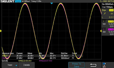
The final output power test was performed at the end of my restoration. The receiver was loaded with a low inductance 8Ω/100W dummy resistor for each channel. The oscilloscope was connected across the speaker terminals and a sine-wave signal of 1kHz was applied to the AUX jacks. The output sine-wave signal was perfectly symmetrical on both channels with no clipping up to 11.51 VRMS (left channel) and 11.40 VRMS (right channel). It corresponds to the output power of 16.6W on the left channel and 16.2W on the right channel.
Output power test
As usual, all the knobs and the front panel were gently cleaned in warm water with dish soap. All controls have been cleaned with DeoxIT 5% contact cleaner and lubricated with DeoxIT FaderLube 5% spray.
The final result can be seen in the photos below. The receiver looks and sounds great! Please watch a short demo video at the end of this post. Thank you for reading.
Marantz 2215B - after restoration


_before%20servicing.jpg)
_after%20servicing.jpg)
_before%20servicing.jpg)
_after%20servicing.jpg)
_before%20servicing.jpg)
_after%20servicing.jpg)
_before%20servicing.jpg)
_after%20servicing.jpg)


_Original%20and%20new%202SA798.jpg)
_before%20servicing.jpg)
_after%20servicing.jpg)
_TR708%20cracked.jpg)
_before%20servicing.jpg)
_after%20servicing.jpg)
_before%20servicing.jpg)
_after%20servicing.jpg)
_A%20low-profile%20heat%20sink%20mounted%20on%20new%20TR707.jpg)
_New%20speaker%20protection%20relay.jpg)
_before%20servicing.jpg)
_close%20look_01_before%20servicing.jpg)
_close%20look_02_before%20servicing.jpg)
_after%20servicing.jpg)
_close%20look_01_after%20servicing.jpg)
_close%20look_02_after%20servicing.jpg)


_25A%20automotive%20fuses.jpg)
_after%20servicing.jpg)


