Unit: AM/FM Stereo Receiver
Manufacturer: Sansui
Model: 2000X
SN: 812030260
Today I'm showcasing a Sansui 2000X receiver that came in for restoration. It was manufactured from 1971 to 1973 and produces 39 watts per channel into 8 ohms with no more than 0.8% total harmonic distortion. The frequency response is pretty impressive from 20Hz to 40kHz. The damping factor is 24.
According to the Sansui database, this particular unit was manufactured in March 1972.
Ripple Filter Block (F-1195-1)
This board has four aluminum electrolytic capacitors: C005, C006, C007, and C015. All of them were replaced with low impedance Nichicon UPW caps. The voltage rating was increased one step up on all capacitors.
Test results on original capacitors removed from the ripple filter block:
C005: rated capacitance – 220uF, measured – 248uF, ESR – 0.09Ω, deviation: +13%
C006: rated capacitance – 330uF, measured – 393uF, ESR – 0.08Ω, deviation: +19%
C007: rated capacitance – 330uF, measured – 376uF, ESR – 0.11Ω, deviation: +14%
C015: rated capacitance – 220uF, measured – 243uF, ESR – 0.08Ω, deviation: +11%
Ripple filter block - before and after
Rectifier Block (F-1197)
This board has only two aluminum electrolytic capacitors: C001 and C002. Both of them were replaced with low impedance UPW/UPM caps.
Driver Amplifier Board (F-1180)
The driver amplifier board has twelve aluminum electrolytic capacitors (C802 thru C807, C812 thru C817). Two of them (C804 & C814) are installed in the signal path. I replaced them with high-quality film polyester WIMA caps to improve the signal-to-noise ratio. The remaining aluminum e-caps were replaced with low impedance Nichicon UPW caps.
Test results on original capacitors removed from the driver amplifier board:
C802: rated capacitance – 100uF, measured – 120uF, ESR – 0.26Ω, deviation: +20%
C803: rated capacitance – 220uF, measured – 255uF, ESR – 0.25Ω, deviation: +16%
C804: rated capacitance – 1uF, measured – 1.1uF, ESR – 2.4Ω, deviation: +10%
C805: rated capacitance – 33uF, measured – 36uF, ESR – 0.32Ω, deviation: +9%
C806: rated capacitance – 100uF, measured – 114uF, ESR – 0.22Ω, deviation: +14%
C807: rated capacitance – 10uF, measured – 13uF, ESR – 0.81Ω, deviation: +30%
C812: rated capacitance – 100uF, measured – 129uF, ESR – 0.24Ω, deviation: +29%
C813: rated capacitance – 220uF, measured – 249uF, ESR – 0.24Ω, deviation: +13%
C814: rated capacitance – 1uF, measured – 1uF, ESR – 3.6Ω, deviation: 0%
C815: rated capacitance – 33uF, measured – 36uF, ESR – 0.33Ω, deviation: +9%
C816: rated capacitance – 100uF, measured – 117uF, ESR – 0.21Ω, deviation: +17%
C817: rated capacitance – 10uF, measured – 14uF, ESR – 0.92Ω, deviation: +40%
Two NPN transistors (TR801 & TR806) installed on this board are the notorious 2SC458LG. This transistor is prone to noise and I replaced both 2SC458LG with new Fairchild KSC1845. The new KSC1845 is a low-noise AF amplifier and is commonly used to replace noisy 2SC458LG transistor. Watch the pinout on replacement transistors if you need to service this board. The original transistor is BCE and the new is ECB.
Driver amplifier board (F-1180) - before and after
Tone Control Board (F-1222-1)
The tone control board has four low leakage e-caps (C707, C715, C721, C729) installed in the signal path, two axial aluminum e-caps (C712, C726), and seven radial aluminum e-caps (C703, C704, C706, CC714, C718, C720, C728). The original low leakage capacitors were replaced with film polyester WIMA caps. Two axial e-caps were replaced with new axial Vishay (138 AML series) capacitors. And, the remaining aluminum e-caps were replaced with low impedance Nichicon UPW caps.
Test results on original capacitors removed from the tone control board:
C703: rated capacitance – 220uF, measured – 244uF, ESR – 0.15Ω, deviation: +11%
C704: rated capacitance – 33uF, measured – 37uF, ESR – 1.28Ω, deviation: +12%
C706: rated capacitance – 33uF, measured – 37uF, ESR – 0.76Ω, deviation: +12%
C707: rated capacitance – 1uF, measured – 1uF, ESR – 1.75Ω, deviation: 0%
C712: rated capacitance – 10uF, measured – 12uF, ESR – 1.21Ω, deviation: +20%
C714: rated capacitance – 47uF, measured – 61uF, ESR – 1.32Ω, deviation: +30%
C715: rated capacitance – 1uF, measured – 1uF, ESR – 2.6Ω, deviation: 0%
C718: rated capacitance – 33uF, measured – 36uF, ESR – 1.31Ω, deviation: +9%
C720: rated capacitance – 33uF, measured – 38uF, ESR – 0.77Ω, deviation: +15%
C721: rated capacitance – 1uF, measured – 1uF, ESR – 2.2Ω, deviation: 0%
C726: rated capacitance – 10uF, measured – 14uF, ESR – 1.06Ω, deviation: +40%
C728: rated capacitance – 47uF, measured – 68uF, ESR – 1.31Ω, deviation: +45%
C729: rated capacitance – 1uF, measured – 1uF, ESR – 2.6Ω, deviation: 0%
Six NPN transistors (TR701 thru TR706) installed on this board are the notorious 2SC458LG. I replaced them with a new Fairchild KSC1845. The new transistors were gain matched within 1%. Again, watch the pinout on replacement transistors if you need to service this board.
Tone control board - before and after
Equalizer Amplifier Board (F-1253)
The equalizer amplifier board has eleven aluminum electrolytic capacitors: C601, C603, C604, C606, C607, C611, C613, C614, C616, C617, and C626. Two of them (C601 & C611) are solid aluminum e-caps installed in the input signal path. I replaced them with film polyester WIMA caps. The other two capacitors (C607 & C617) installed in the output signal path are just ordinary aluminum e-caps. These were replaced with low leakage Nichicon UKL caps. The remaining aluminum capacitors were replaced with low impedance Nichicon UPW caps.
Test results on original capacitors removed from the equalizer amplifier board:
C601: rated capacitance – 1.5uF, measured – 1.7uF, ESR – 4.4Ω, deviation: +13%
C603: rated capacitance – 33uF, measured – 36uF, ESR – 1.32Ω, deviation: +9%
C604: rated capacitance – 33uF, measured – 35uF, ESR – 1.35Ω, deviation: +6%
C606: rated capacitance – 47uF, measured – 59uF, ESR – 1.36Ω, deviation: +26%
C607: rated capacitance – 10uF, measured – 13uF, ESR – 1.86Ω, deviation: +30%
C611: rated capacitance – 1.5uF, measured – 1.4uF, ESR – 2.6Ω, deviation: -7%
C613: rated capacitance – 33uF, measured – 36uF, ESR – 1.33Ω, deviation: +9%
C614: rated capacitance – 33uF, measured – 36uF, ESR – 1.38Ω, deviation: +9%
C616: rated capacitance – 47uF, measured – 56uF, ESR – 1.57Ω, deviation: +19%
C617: rated capacitance – 10uF, measured – 11uF, ESR – 2.3Ω, deviation: +10%
C626: rated capacitance – 100uF, measured – 122uF, ESR – 0.51Ω, deviation: +22%
Four NPN transistors installed on this board are prone to noise 2SC871. I replaced them with a new Fairchild KSC1845. The new transistors were gain matched within 1%. Watch the pinout on replacement transistors if you need to service this board. The original transistor is BCE and the new is ECB.
Equalizer amplifier board - before and after
AM Meter Block (F-1220-1)
The AM meter block has two aluminum electrolytic capacitors: C335 and C345. The C345 is soldered on the foil side between the wiper terminal and the ground. The original capacitor C335 was replaced with a low impedance Nichicon UPW cap. The original capacitor C345 was replaced with a film polyester WIMA cap.
Test results on original capacitors removed from the AM meter block:
C335: rated capacitance – 4.7uF, measured – 7.3uF, ESR – 1.82Ω, deviation: +55%
C345: rated capacitance – 1uF, measured – 1.1uF, ESR – 2.8Ω, deviation: +10%
AM meter block - before servicing
AM meter block - after servicing
Accessories Block (F-1254-1)
The accessories block has only two aluminum electrolytic capacitors: C739 and C740. It is possible to replace these capacitors without disassembling the board from the chassis. I replaced them with film polyester WIMA caps. Sorry, I didn't take a picture of this board.
Test results on original capacitors removed from the accessories block:
C739: rated capacitance – 0.47uF, measured – 0.45uF, ESR – N/A, deviation: -4%
C740: rated capacitance – 0.47uF, measured – 0.51uF, ESR – N/A, deviation: +9%
Dial and Meter Lamps
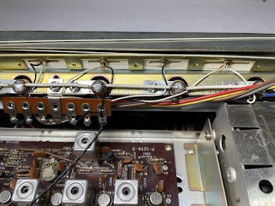
The dial and meter lamps in this unit were replaced with new incandescent lamps (6V, 0.25A, screw base). The dial lamps can be accessed from the front panel when the scale is removed.
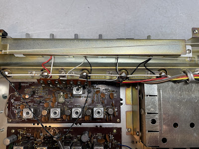
The stereo indicator and one function indicator lamp were blown out in this unit. I replaced them with new incandescent lamps as well. Access to these lamps is very limited and additional disassembling is required (at least the cover plate should be removed).
The cover plate removed to access the stereo indicator and function indicator lamps
New Stereo and AUX indicator lamps were installed
Idling Current and Symmetrical Clipping Adjustments
The idling current was adjusted to ~15mA on each channel according to the service manual. Two large trimming resistors (VR802 & VR804, 1kΩ each) are used for idling current adjustment.
Two small trimming resistors (VR801 & VR803, 200kΩ each) are used to adjust an equal clipping of the 1 kHz sine-wave signal.
Idling current on the left and right channels after restoration
Output Power Test
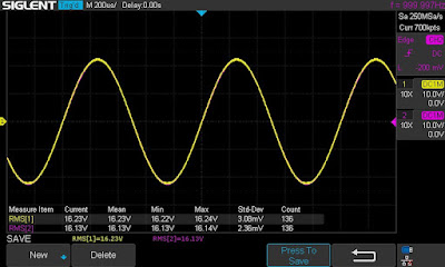
The final output power test was performed at the end of my restoration. The amplifier was loaded with a low inductance 8Ω/100W dummy resistor for each channel. The oscilloscope was connected across the speaker terminals and a sine-wave signal of 1kHz was applied to the AUX jacks. The output sine-wave signal was perfectly symmetrical on both channels with no clipping up to 16.23 VRMS (left channel) and 16.13 VRMS (right channel). It corresponds to the output power of 32.9W on the left channel and 32.5W on the right channel.
Output power test
As usual, all the knobs and the front panel were gently cleaned in warm water with dish soap. All controls have been cleaned with DeoxIT 5% contact cleaner and lubricated with DeoxIT FaderLube 5% spray. The wood case was stained with Howard's Restor-A-Finish.
The final result can be seen in the photos below. The receiver looks brand new again and sounds fantastic! Classic Sansui receiver from the 70's! Please watch a short demo video at the end of this post. Thank you for reading.
Sansui 2000X - after restoration


_before%20servicing.jpg)
_after%20servicing.jpg)
_before%20servicing.jpg)
_after%20servicing.jpg)
_before%20servicing.jpg)
_after%20servicing.jpg)
_before%20servicing.jpg)
_after%20servicing.jpg)
_before%20servicing.jpg)
_after%20servicing.jpg)
_before%20servicing.jpg)
_foil%20side_before%20servicing.jpg)
_after%20servicing.jpg)
_foil%20side_after%20servicing.jpg)


Do you restore Sansui 5000A? I have 2 that still sound great but have never been recapped. One is from 1969 and the other is from 1970. I’m driving a pair of 1977 McIntosh ML10Cs with one, and a single 1957 JBL C40 Harkness Lowboy with rear loaded 6 foot folded horn, original 130A woofer (with the black voice cool cover, the D130 had an aluminum one). Original 175DLH, and original N1200 crossover which i just recapped by removing the 3 film caps and installing all polypropylene capacitor. The sound is just pristine!
ReplyDelete