Unit: AM/FM Stereo Receiver
Manufacturer: Yamaha
Model: CR-1020
SN: 01592
Another classic receiver from the 70's came on my bench for a full restoration. The Yamaha CR-1020 natural sound AM/FM receiver is the younger brother of the CR-2020 and CR-3020. It was manufactured from 1977 to 1980. It produces 70 watts per channel into 8 ohms with no more than 0.05% total harmonic distortion. This particular unit is from a private collection and came in excellent cosmetic condition. The wood case, front panel, and knobs are almost flawless.
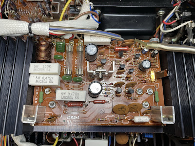
Electrolytic Cap Board (NA 06903)
The electrolytic cap board has one low leakage e-cap (C813) and three aluminum electrolytic capacitors (C805, C806, C817). The original low leakage e-cap was replaced with modern low leakage Nichicon UKL cap. The remaining aluminum capacitors were replaced with low impedance Nichicon UPW/UPM caps. The original electronic capacitors removed from this board have been tested with an Atlas ESR70 capacitance meter and the results are shown below. Only one capacitor is out of factory tolerance spec.
Test results on original capacitors removed from the electrolytic cap board:
C805: rated capacitance – 1000uF, measured – 824uF, ESR – 0.01Ω, deviation: -18%
C806: rated capacitance – 1000uF, measured – 753uF, ESR – 0.01Ω, deviation: -25%
C813: rated capacitance – 100uF, measured – 107uF, ESR – 0.08Ω, deviation: +7%
C817: rated capacitance – 220uF, measured – 189uF, ESR – 0.04Ω, deviation: -14%
Two large filter capacitors (C811/C812, 15000uF/63V) are also located on this board. I tested them in-circuit with a capacitance meter and they both are still in spec. So, I didn't change them. In general, the filter capacitors rarely fail in vintage gears, and I usually don't replace them unless their ESR is high.
In-circuit test on two filter capacitors - both are still in spec
C811: rated capacitance – 15000uF, measured – 13360uF, ESR – 0.01Ω, deviation: -11%
C812: rated capacitance – 15000uF, measured – 14200uF, ESR – 0.01Ω, deviation: -5%
The original fusible resistors FR801 & FR802 change the resistance value over time. It might result in intermittent power supply failure. I replaced them with Ohmite 22Ω 3 1/4 watt resistors according to the service bulletin for CR-2020.
The transformer was disassembled from the chassis to access the foil side of the PCB
Electrolytic cap board - before and after
Power Supply Board - 1 (NA 06899-1)
Two regulator transistors (TR712 and TR715) on the power supply board are running very hot under normal operating conditions. Eventually, these transistors often break down due to overheating. The original transistors installed in these positions are 2SD234. I replaced them with Fairchild MJE15030G and refresh the thermal paste between each transistor and heat sink. The collector power dissipation of the new Fairchild transistor is 50W whereas the original 2SD234 can dissipate only 25W. It will improve the reliability of the power supply circuit in this unit.
PCB under the heat sink with transistor TR712 - original transistor suffers from overheating
PCB under the heat sink with transistor TR712 - after cleaning
There are 31 aluminum electrolytic capacitors on the power supply board. All of them were replaced with low impedance Nichicon UPW caps.
Test results on original capacitors removed from the power supply board:
C701: rated capacitance – 10uF, measured – 13uF, ESR – 2.01Ω, deviation: +30%
C702: rated capacitance – 10uF, measured – 13uF, ESR – 2.11Ω, deviation: +30%
C703: rated capacitance – 10uF, measured – 11uF, ESR – 2.2Ω, deviation: +10%
C704: rated capacitance – 10uF, measured – 11uF, ESR – 1.71Ω, deviation: +10%
C705: rated capacitance – 10uF, measured – 13uF, ESR – 1.85Ω, deviation: +30%
C706: rated capacitance – 10uF, measured – 13uF, ESR – 1.97Ω, deviation: +30%
C707: rated capacitance – 3.3uF, measured – 4.0uF, ESR – 2.4Ω, deviation: +21%
C708: rated capacitance – 3.3uF, measured – 3.8uF, ESR – 2.01Ω, deviation: +15%
C709: rated capacitance – 100uF, measured – 93uF, ESR – 0.61Ω, deviation: -7%
C710: rated capacitance – 100uF, measured – 95uF, ESR – 0.57Ω, deviation: -5%
C711: rated capacitance – 47uF, measured – 52uF, ESR – 1.04Ω, deviation: +11%
C712: rated capacitance – 47uF, measured – 53uF, ESR – 1.42Ω, deviation: +13%
C713: rated capacitance – 100uF, measured – 118uF, ESR – 0.71Ω, deviation: +18%
C714: rated capacitance – 100uF, measured – 108uF, ESR – 0.51Ω, deviation: +8%
C717: rated capacitance – 100uF, measured – 104uF, ESR – 3.4Ω, deviation: +4%
C718: rated capacitance – 10uF, measured – 11uF, ESR – 1.73Ω, deviation: +10%
C719: rated capacitance – 10uF, measured – 11uF, ESR – 1.52Ω, deviation: +10%
C720: rated capacitance – 10uF, measured – 11uF, ESR – 1.45Ω, deviation: +10%
C721: rated capacitance – 10uF, measured – 11uF, ESR – 1.21Ω, deviation: +10%
C722: rated capacitance – 10uF, measured – 11uF, ESR – 2.8Ω, deviation: +10%
C728: rated capacitance – 220uF, measured – 237uF, ESR – 0.24Ω, deviation: +8%
C729: rated capacitance – 1000uF, measured – 1196uF, ESR – 0.02Ω, deviation: +20%
C730: rated capacitance – 100uF, measured – 102uF, ESR – 0.42Ω, deviation: +2%
C732: rated capacitance – 220uF, measured – 251uF, ESR – 0.31Ω, deviation: +14%
C733: rated capacitance – 10uF, measured – 11uF, ESR – 3.4Ω, deviation: +10%
C734: rated capacitance – 47uF, measured – 50uF, ESR – 3.1Ω, deviation: +6%
C735: rated capacitance – 22uF, measured – 26uF, ESR – 0.98Ω, deviation: +18%
C736: rated capacitance – 22uF, measured – 26uF, ESR – 1.02Ω, deviation: +18%
C737: rated capacitance – 4.7uF, measured – 5.5uF, ESR – 2.5Ω, deviation: +17%
C738: rated capacitance – 47uF, measured – 28uF, ESR – 1.21Ω, deviation: -40%
C740: rated capacitance – 47uF, measured – 51uF, ESR – 0.78Ω, deviation: +9%
Power supply board - before and after
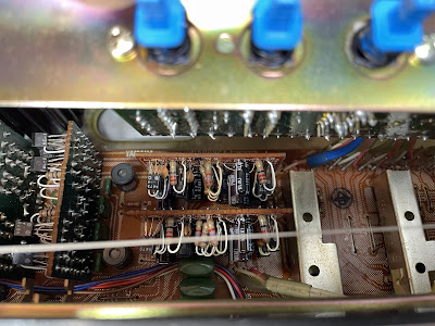
Pre Module Boards: A, B, C, D, and E
Five pre module boards (A, B, C, D, and E) are vertically mounted on the tone control board. All pre module boards can be easily removed from the tone control board for servicing if unsolder seven pins from each board.
The tone control board has only two low leakage e-caps C405 and C406 installed in the signal path. I replaced them with modern low leakage Nichicon UKL caps.
The pre module boards A and B are identical (NA 06898-1) and have three low leakage e-caps (C502, C509, C510) installed in the signal path and three aluminum e-caps (C504, C505, C508). All original low leakage e-caps were replaced with modern low leakage Nichicon UKL caps. The remaining aluminum capacitors were replaced with low impedance Nichicon UPW caps.
Test results on original capacitors removed from the pre module boards A and B:
C502: rated capacitance – 10uF, measured – 8uF, ESR – 2.4Ω, deviation: -10%
C504: rated capacitance – 100uF, measured – 114uF, ESR – 0.33Ω, deviation: +14%
C505: rated capacitance – 220uF, measured – 279uF, ESR – 0.22Ω, deviation: +27%
C508: rated capacitance – 100uF, measured – 106uF, ESR – 0.28Ω, deviation: +6%
C509: rated capacitance – 22uF, measured – 20uF, ESR – 0.66Ω, deviation: -9%
C510: rated capacitance – 100uF, measured – 122uF, ESR – 0.18Ω, deviation: +22%
C502: rated capacitance – 10uF, measured – 9uF, ESR – 2.2Ω, deviation: -10%
C504: rated capacitance – 100uF, measured – 131uF, ESR – 0.46Ω, deviation: +31%
C505: rated capacitance – 220uF, measured – 213uF, ESR – 0.55Ω, deviation: -3%
C508: rated capacitance – 100uF, measured – 105uF, ESR – 0.22Ω, deviation: +5%
C509: rated capacitance – 22uF, measured – 22uF, ESR – 0.21Ω, deviation: 0%
C510: rated capacitance – 100uF, measured – 130uF, ESR – 0.23Ω, deviation: +30%
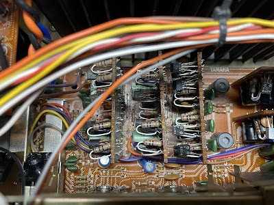
Pre module boards: A and B - mounted vertically on the tone control board
Pre module boards A and B (NA 06898-1) - before and after
The pre module board C has no electrolytic capacitors or noisy/trouble transistors.
The pre module boards D and E are identical (NA 06898-3) and have six low leakage e-caps (C571 thru C574, C579, C580) installed in the signal path. All of them were replaced with modern low leakage Nichicon UKL caps.
Test results on original capacitors removed from the pre module boards D and E:
C571: rated capacitance – 10uF, measured – 8uF, ESR – 2.4Ω, deviation: -20%
C572: rated capacitance – 10uF, measured – 8uF, ESR – 2.2Ω, deviation: -20%
C573: rated capacitance – 10uF, measured – 8uF, ESR – 2.2Ω, deviation: -20%
C574: rated capacitance – 10uF, measured – 9uF, ESR – 2.2Ω, deviation: -10%
C579: rated capacitance – 22uF, measured – 21uF, ESR – 0.29Ω, deviation: -5%
C580: rated capacitance – 22uF, measured – 21uF, ESR – 0.71Ω, deviation: -5%
C571: rated capacitance – 10uF, measured – 8uF, ESR – 2.7Ω, deviation: -20%
C572: rated capacitance – 10uF, measured – 8uF, ESR – 2.6Ω, deviation: -20%
C573: rated capacitance – 10uF, measured – 9uF, ESR – 2.9Ω, deviation: -10%
C574: rated capacitance – 10uF, measured – 9uF, ESR – 2.6Ω, deviation: -10%
C579: rated capacitance – 22uF, measured – 20uF, ESR – 0.41Ω, deviation: -9%
C580: rated capacitance – 22uF, measured – 24uF, ESR – 0.42Ω, deviation: +9%
Pre module boards: C, D, and E - mounted vertically on the tone control board
Tuner Board - 1
The phono equalizer circuit is a part of the tuner board - 1. This circuit has four low leakage e-caps installed in the input (C303, C304) and output (C327, C328) signal path, and eight aluminum electrolytic capacitors (C305, C306, C309, C310, C317, C318, C321, C322). All original low leakage e-caps were replaced with modern low leakage Nichicon UKL caps. The remaining aluminum e-caps were replaced with low impedance Nichicon UPW caps.
Test results on original capacitors removed from the phono equalizer circuit:
C303: rated capacitance – 10uF, measured – 8uF, ESR – 2.7Ω, deviation: -20%
C304: rated capacitance – 10uF, measured – 9uF, ESR – 2.4Ω, deviation: -10%
C305: rated capacitance – 2.2uF, measured – 2.1uF, ESR – 2.4Ω, deviation: -5%
C306: rated capacitance – 2.2uF, measured – 2.3uF, ESR – 1.9Ω, deviation: +5%
C309: rated capacitance – 220uF, measured – 218uF, ESR – 0.59Ω, deviation: -1%
C310: rated capacitance – 220uF, measured – 212uF, ESR – 0.62Ω, deviation: -4%
C317: rated capacitance – 470uF, measured – 531uF, ESR – 0.25Ω, deviation: +13%
C318: rated capacitance – 470uF, measured – 554uF, ESR – 0.32Ω, deviation: +18%
C321: rated capacitance – 100uF, measured – 103uF, ESR – 0.36Ω, deviation: +3%
C322: rated capacitance – 100uF, measured – 108uF, ESR – 0.52Ω, deviation: +8%
C327: rated capacitance – 10uF, measured – 9uF, ESR – 2.2Ω, deviation: -10%
C328: rated capacitance – 10uF, measured – 9uF, ESR – 2.6Ω, deviation: -10%
Phono equalizer circuit - before and after
Main Board
The main board has one low leakage capacitor (C601) installed in the signal path and four aluminum e-caps (C605, C613, C614, C615). The original low leakage e-cap was replaced with modern low leakage Nichicon UKL cap. The remaining aluminum e-caps were replaced with low impedance Nichicon UPW/UPM caps.
Test results on original capacitors removed from the main board:
Left channel:
C601: rated capacitance – 10uF, measured – 8uF, ESR – 2.1Ω, deviation: -20%
C605: rated capacitance – 220uF, measured – 227uF, ESR – 0.32Ω, deviation: +3%
C613: rated capacitance – 10uF, measured – 12uF, ESR – 1.62Ω, deviation: +20%
C614: rated capacitance – 47uF, measured – 52uF, ESR – 0.11Ω, deviation: +11%
C615: rated capacitance – 100uF, measured – 109uF, ESR – 0.18Ω, deviation: +9%
Right channel:
C601: rated capacitance – 10uF, measured – 9uF, ESR – 2.7Ω, deviation: -10%
C605: rated capacitance – 220uF, measured – 221uF, ESR – 0.54Ω, deviation: 0%
C613: rated capacitance – 10uF, measured – 13uF, ESR – 1.55Ω, deviation: +30%
C614: rated capacitance – 47uF, measured – 54uF, ESR – 0.32Ω, deviation: +15%
C615: rated capacitance – 100uF, measured – 107uF, ESR – 0.13Ω, deviation: +7%
The original trimming resistors VR601 (4.7Ω/0.5W, x2) were replaced with new Bourns potentiometers.
All power transistors were removed from the heat sink, cleaned, and tested. The measured DC current gain was in spec according to the datasheet. I applied a fresh thermal compound and replaced the old thermal pads with new Mica ones.
Main board - before and after (left and right boards are identical)
Dial and Meter Lamps
Three meters in the CR-1020 are illuminated with four incandescent lamps. Two of them were burned out. I replaced all of them with new incandescent lamps.
There is no backlit to the dial scale in CR-1020 but the dial pointer is illuminated. And unlike many other vintage receivers, it's relatively easy to replace the burned pointer bulb on this model. One just needs to unscrew two small screws on the top of the dial pointer unit and the lamp will be released.
Original dial pointer lamp - disassembled from the holder
A new lamp was installed
Bias Adjustment
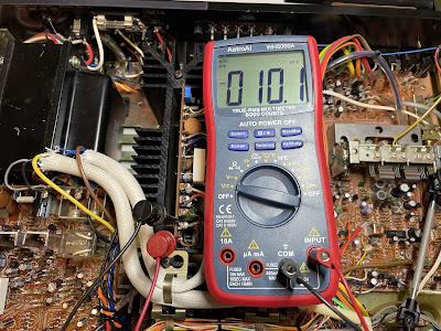
The Bias is measured across the emitter resistor R631 (0.47Ω, 5W). The voltmeter should be connected between pins TP1 and 0 on the main board. The Bias should be adjusted to ~10mV with the trimming resistor VR601. It corresponds to the idling current of ~21mA (=10mV/0.47Ω).
Bias on the left and right channels after restoration
Power Meter Adjustment
An AC voltmeter and function generator are required to adjust power meters. A sine-wave signal of 1 kHz should be applied to the AUX terminals and the level of this signal should be adjusted so that the voltage on the SPEAKERS terminals read 20 VRMS. Then, the trimming resistors VR701 and VR702 should be adjusted so that the power meters read 50W.
Output Power Test
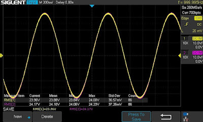
The final output power test was performed at the end of my restoration. The amplifier was loaded with a low inductance 8Ω/100W dummy resistor for each channel. The oscilloscope was connected across the speaker terminals and a sine-wave signal of 1kHz was applied to the AUX jacks. The output sine-wave signal was perfectly symmetrical on both channels with no clipping up to 23.96 VRMS (left channel) and 24.17 VRMS (right channel). It corresponds to the output power of 71.8W on the left channel and 73.0W on the right channel.
Output power test
As usual, all the knobs and the front panel were gently cleaned in warm water with dish soap. All controls have been cleaned with DeoxIT 5% contact cleaner and lubricated with DeoxIT FaderLube 5% spray. The wood case was stained with Howard's Restor-A-Finish.
The final result can be seen in the photos below. The receiver looks brand new again and sounds fantastic! Please watch a short demo video at the end of this post. Thank you for reading.
Yamaha CR-1020 - after restoration


_before.jpg)
_after.jpg)


_before.jpg)
_after.jpg)
_before%20servicing.jpg)
_after%20servicing.jpg)
_before%20servicing.jpg)
_after%20servicing.jpg)







Awesome write up! Thanks for putting this together.
ReplyDeleteVery informative!
ReplyDelete