Unit: AM/FM Stereo Receiver
Manufacturer: Marantz
Model: 2252B
SN: U090603
Today I'm showcasing a Marantz 2252B vintage receiver that came in for restoration. The owner bought this receiver new in 1980 at Pacific Stereo in Houston, TX. The unit arrived in pretty rough condition with multiple issues.
- All pots and switches are very dirty. The sound is scratchy and distorted.
- The left channel is faint.
- The tuner selectivity is bad.
- The protection relay is in bad condition (a lot of arcing when engaged).
- The power amplifier & power supply board has some discoloration due to excess heat.
- Three dial and both meter lamps are burned out.
- The dial pointer lamp is burned out.
- The Stereo indicator lamp is burned out.
- The lamp reflector is broken into several pieces.
- Four plastic feet are completely destroyed.
Marantz 2252B was manufactured from 1977 to 1980. It produces 52 watts per channel into 8 ohms with no more than 0.05% total harmonic distortion. The optional walnut veneer cabinet for this model is WC-122.
According to the factory stamp on the chassis, this unit was manufactured in March 1978.
Okay, it’s time to rock and roll. Let's bring it back to life, step by step to its initial condition. This receiver deserves it.
Power Amplifier & Power Supply Board (P700)
The power supply, protection circuit, and power amplifier in Marantz 2252B are all located on a single PCB. This design is similar to that in Marantz 2238B which I restored about a year ago. To service this board one should remove four power transistors, disassemble the heat sink from the chassis, remove the speaker switch extension shafts, and finally unsolder several very short wires between the PCB and two filter capacitors. Sounds like a lot of fun, doesn't it?
The regulated power supply circuit has six aluminum e-caps C733, C734, C735, C737, C738, and C739. All of them were replaced with low impedance and high-reliability Nichicon UPW/UPM caps.
The original e-caps removed from this board were tested with an Atlas ESR70 capacitance meter and the results are below. Three out of six original e-caps failed the test (open circuit/low capacitance)!
Test results on original capacitors removed from the power supply circuit:
C733: rated capacitance – 470uF, measured – 431uF, ESR – 0.01Ω, deviation: -8%
C734: rated capacitance – 100uF, measured – 114uF, ESR – 0.04Ω, deviation: +14%
C735: rated capacitance – 33uF, measured – open circuit/low capacitance
C737: rated capacitance – 100uF, measured – open circuit/low capacitance
C738: rated capacitance – 10uF, measured – open circuit/low capacitance
C739: rated capacitance – 1000uF, measured – 1114uF, ESR – 0.02Ω, deviation: +11%
I also noticed the PCB discoloration around two transistors Q750 and Q751. One of them (Q750) was replaced in the past with a 2SC1567 transistor. I decided to replace both transistors to improve the reliability of the power supply circuit. The Q750 was replaced with a new Fairchild KSC2690AYSTU and Q751 with a new Fairchild KSC2383YTA.
The protection circuit has two aluminum e-caps C730, C731, and one low leakage e-cap C740. The low leakage e-cap is soldered on the back (foil) side of the PCB. Two aluminum e-caps were replaced with low impedance Nichicon UPW caps. The e-cap C740 was replaced with a modern low leakage Nichicon UKL cap.
Test results on original capacitors removed from the protection circuit:
C730: rated capacitance – 47uF, measured – 49uF, ESR – 0.34Ω, deviation: +4%
C731: rated capacitance – 330uF, measured – 416uF, ESR – 0.08Ω, deviation: +26%
C740: rated capacitance – 10uF, measured – 11uF, ESR – 0.46Ω, deviation: +10%
The e-cap C740 soldered on the back (foil) side of the PCB
The PCB discoloration was also observed around three transistors (Q743, Q744, and Q745) and 1/4W resistors (R771, R774, R775). I decided to replace all of them as well. The original transistors Q743 and Q744 were replaced with new Fairchild KSC945CYTA. While the original Q745 was replaced with a new Fairchild KSC2383YTA. All original transistors were tested with Atlas DCA55 semiconductor analyzer. Two of them (Q743 and Q744) are still in spec but the Q745 has a very low current gain of 51. According to the datasheet, this transistor should have a current gain of at least 120 (2SC1318, rank R or S). The original 1/4W resistors were replaced with new 1/2W KOA Speer metal film resistors.
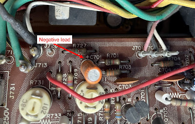
The main amplifier circuit has eight low leakage e-caps C701, C702, C705, C706, C719 thru C722, and three aluminum e-caps C709, C710, and C729. All original low leakage e-caps were replaced with modern low leakage Nichicon UKL capacitors. Pay attention to the polarity of e-cap C701. The polarity on the silkscreen is backward! Also, there is a discrepancy with four low leakage capacitors C719 thru C722. According to the schematic, these capacitors are rated at 22uF/16V. The service manual says they are 10uF/16V. The original capacitors installed in these positions were 22uF/16V. So, I replaced them with new Nichicon UKL capacitors (22uF/16V). The remaining aluminum e-caps (C709, C710, and C729) were replaced with low impedance Nichicon UPW caps.
All original e-caps removed from this board were tested with an Atlas ESR70 capacitance meter and the results are below. As can be seen, the original e-cap C701 failed the test (open circuit/low capacitance)! This capacitor is installed in the input signal path and was the main reason for the faint sound in the left channel.
Test results on original capacitors removed from the main amplifier circuit:
C701: rated capacitance – 3.3uF, measured – open circuit/low capacitance
C702: rated capacitance – 3.3uF, measured – 2.2uF, ESR – 7.1Ω, deviation: -33%
C705: rated capacitance – 47uF, measured – 29uF, ESR – 12.4Ω, deviation: -38%
C706: rated capacitance – 47uF, measured – 42uF, ESR – 0.59Ω, deviation: -11%
C709: rated capacitance – 47uF, measured – 54uF, ESR – 0.31Ω, deviation: +15%
C710: rated capacitance – 47uF, measured – 50uF, ESR – 0.11Ω, deviation: +6%
C719: rated capacitance – 22uF, measured – 24uF, ESR – 0.86Ω, deviation: +9%
C720: rated capacitance – 22uF, measured – 22uF, ESR – 0.94Ω, deviation: 0%
C721: rated capacitance – 22uF, measured – 22uF, ESR – 1.36Ω, deviation: 0%
C722: rated capacitance – 22uF, measured – 17uF, ESR – 3.1Ω, deviation: -23%
C729: rated capacitance – 220uF, measured – 222uF, ESR – 0.02Ω, deviation: +1%
The polarity of e-cap C701 is backward on the silkscreen
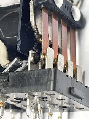
As I mentioned earlier, the original protection relay was in bad condition. I unsoldered it from the PCB and removed the cover. As expected all contacts were toasted. I replaced it with a new Omron relay.
Original protection relay - all contacts are in bad condition
Power amplifier & power supply board - before servicing
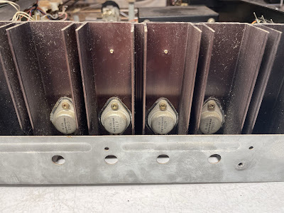
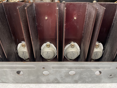
Power Transistors
Four power transistors were removed, degreased, and tested with Atlas DCA55 semiconductor analyzer. The measured DC current gain on all transistors was in spec according to the datasheet. However, it should be noted that Atlas DCA55 semiconductor analyzer provides the accurate reading for DC current gain only on low-power transistors. A high-power transistor requires a much higher collector current and collector-emitter voltage to accurately measure its current gain. However, it is still a very useful device for comparing transistors of a similar type for the purposes of gain matching or fault-finding.
I applied a fresh thermal compound and replaced the old thermal pads with new Mica ones which is always a good idea when working on any vintage receiver. The old grease can frequently dry, causing the transistors to suffer from poor heat dissipation. This can result in overheating and the destruction of the device.
Four power transistors - before and after
Phono Amplifier Board (P400)
The phono amplifier board has six low leakage e-caps (C401, C402, C407, C408, C415, C416) and four aluminum e-caps (C411, C412, C421, C422). All low leakage e-caps were replaced with modern low leakage Nichicon UKL caps. The remaining aluminum e-caps were replaced with low impedance Nichicon UPW/UPM caps. This board has no transistors prone to failure or noise. So, no transistors were replaced.
Test results on original capacitors removed from the phono amplifier board:
C401: rated capacitance – 2.2uF, measured – 3.1uF, ESR – 5.8Ω, deviation: +41%
C402: rated capacitance – 2.2uF, measured – 2.9uF, ESR – 2.8Ω, deviation: +32%
C407: rated capacitance – 22uF, measured – 22uF, ESR – 0.91Ω, deviation: 0%
C408: rated capacitance – 22uF, measured – 23uF, ESR – 0.86Ω, deviation: +5%
C411: rated capacitance – 47uF, measured – 52uF, ESR – 0.22Ω, deviation: +11%
C412: rated capacitance – 47uF, measured – 54uF, ESR – 0.13Ω, deviation: +15%
C415: rated capacitance – 2.2uF, measured – 2.0uF, ESR – 2.3Ω, deviation: -9%
C416: rated capacitance – 2.2uF, measured – 2.0uF, ESR – 2.3Ω, deviation: -9%
C421: rated capacitance – 100uF, measured – 100uF, ESR – 0.02Ω, deviation: 0%
C422: rated capacitance – 47uF, measured – 54uF, ESR – 0.43Ω, deviation: +15%
Phono amplifier board - before and after
Tone Amplifier Board (PE01)
It is pretty easy to service the tone amplifier board in Marantz 2252B. This board is mounted on the chassis with four nuts. Just unscrew them and the board is released for service. This design is way better than that implemented in Marantz 2238B where the servicing of the tone board is a real PITA.
The tone amplifier board has six low leakage e-caps (CE05, CE06, CE19, CE20, CE21, CE22), two non-polar e-caps (CE23, CE24), and three aluminum e-caps (CE03, CE04, CE25). The original low leakage e-caps (CE19, CE20) and two non-polar e-caps (CE23, CE24) were replaced with high-quality film polyester WIMA MKS2 caps. The remaining low leakage e-caps were replaced with modern low leakage Nichicon UKL capacitors. Three original aluminum e-caps were replaced with low impedance Nichicon UPW caps.
Test results on original capacitors removed from the tone amplifier board:
CE03: rated capacitance – 22uF, measured – 24uF, ESR – 0.21Ω, deviation: +9%
CE04: rated capacitance – 22uF, measured – 25uF, ESR – 0.27Ω, deviation: +14%
CE05: rated capacitance – 4.7uF, measured – 5.7uF, ESR – 3.5Ω, deviation: +21%
CE06: rated capacitance – 4.7uF, measured – 5.8uF, ESR – 3.4Ω, deviation: +23%
CE19: rated capacitance – 1uF, measured – 0.9uF, ESR – 2.6Ω, deviation: -10%
CE20: rated capacitance – 1uF, measured – 0.9uF, ESR – 2.9Ω, deviation: -10%
CE21: rated capacitance – 3.3uF, measured – 3.3uF, ESR – 2.1Ω, deviation: 0%
CE22: rated capacitance – 3.3uF, measured – 3.3uF, ESR – 1.6Ω, deviation: 0%
CE23: rated capacitance – 1uF, measured – 1uF, ESR – 0.72Ω, deviation: 0%
CE24: rated capacitance – 1uF, measured – 1uF, ESR – 0.65Ω, deviation: 0%
CE25: rated capacitance – 220uF, measured – 195uF, ESR – 0.01Ω, deviation: -11%
Tone amplifier board - before servicing, after cleaning, and after servicing
Filter Capacitors
Two large filter capacitors were tested with Atlas ESR70 capacitance meter. Both caps are still within the factory capacitance tolerance and have very low ESR. So, I didn't change them. In general, the filter capacitors rarely fail in vintage gears, and I usually don't replace them unless their ESR is high.
In-circuit test on two filter capacitors - both are still in spec
C005-1: rated capacitance – 10000uF, measured – 9931uF, ESR – 0.02Ω, deviation: -1%
C005-2: rated capacitance – 10000uF, measured – 9952uF, ESR – 0.02Ω, deviation: -1%
Miscellaneous Issues
- All the dial and both meter lamps were replaced with new warm white LED lamps. For more details, please refer to my previous post regarding the restoration of Marantz 2238B.
- The burned dial pointer lamp was replaced with a new incandescent lamp.
- The burned Stereo indicator lamp was also replaced with a new incandescent lamp.
- The main variable capacitor was cleaned with a non-residue contact cleaner. Then, the CAIG FaderLube was applied to each contact. It restored the selectivity of the tuner.
- I did not find another lamp reflector and decided to seal the broken one. It took some time and patience, but the final result was good. It is strong enough again and does its job.
- Four new Marantz feet made from strong BASF A3W Nylon 6/6 material were installed.
- The old power cord was replaced with a new one. The strain relief bushing was replaced as well.
Power Supply Adjustment
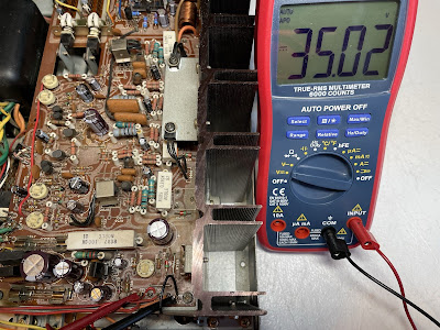
The DC voltage between pins J722 (+) and J728 (ground) was adjusted to +35V with the trimming resistor R787.
DC voltage between pins J722 and J728 under no signal condition
Bias and DC Offset Adjustments
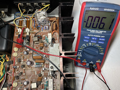
The bias is measured across two emitter resistors (wire wound type, 0.39Ω/5W). The voltage drop across resistors R763 and R765 should be adjusted to ~24mV DC with the trimming resistor R731. This is a bias on the left channel. And on the right channel, the voltage drop across resistors R764 and R766 should be adjusted to ~24mV DC with the trimming resistor R732.
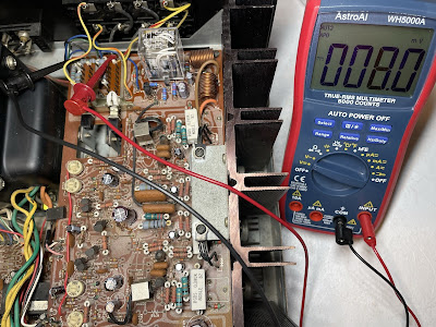
The DC offset is measured between pins J717 and J714 (ground) on the left channel and between pins J718 and J714 (ground) on the right channel. It should be adjusted as close to zero volts as possible with the trimming resistors R711 and R712, respectively.
Bias on the left and right channels after restoration
DC offset on the left and right channels after restoration
Output Power Test
The final output power test was performed at the end of my restoration. The amplifier was loaded with a low inductance 8Ω/100W dummy resistor for each channel. The oscilloscope was connected across the speaker terminals and a sine-wave signal of 1kHz was applied to the AUX jacks. The output sine-wave signal was perfectly symmetrical on both channels with no clipping up to 20.66 VRMS (left channel) and 20.48 VRMS (right channel). It corresponds to the output power of 53.4W on the left channel and 52.4W on the right channel.
Output power test
All the knobs and the faceplate were gently cleaned in warm water with dish soap. All controls have been cleaned with DeoxIT 5% contact cleaner and lubricated with DeoxIT FaderLube 5% spray.
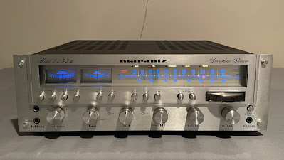
The final result can be seen in the photos below. The receiver looks great again and sounds fantastic! Please watch a short demo video at the end of this post. Thank you for reading.
Marantz 2252B - after restoration


_before%20servicing.jpg)
_after%20servicing.jpg)
_before%20servicing.jpg)
_after%20servicing.jpg)
_before%20servicing.jpg)
_after%20cleaning.jpg)
_after%20servicing.jpg)
