Unit: AM/FM Stereo Receiver
Manufacturer: Pioneer
Model: SX-1010
SN: UA3902361M
Today I'm showcasing a Pioneer SX-1010 stereo receiver that came in for restoration. This is the first real "Monster" receiver introduced to the market in 1974. The SX-1010 is Pioneer's top-of-the-line AM/FM stereo receiver and an important milestone in the history of Hi-Fi audio equipment. This iconic piece of equipment actually triggered the Monster receivers war of the 70's. It produces 100W + 100W continuous RMS power (both channels driven at 8 ohms) with a total harmonic distortion of less than 0.1%, throughout the entire audible spectrum from 20Hz to 20kHz. Power is maintained smoothly and continuously with a direct-coupled circuit driven by dual power supplies. The list price in 1974 was $699.95 (Ref. High Fidelity Magazine, April 1974, page 101).
According to the Pioneer database, this particular unit was manufactured in January 1974.
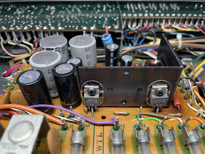
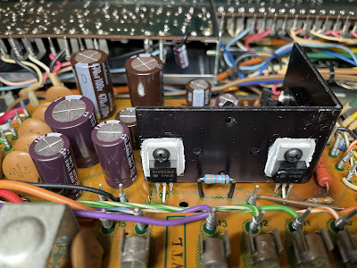
Power Supply Board (AWR-054-A)
The power supply board (AWR-054-A) has eleven aluminum electrolytic capacitors C8 thru C14 and C18 thru C21. I replaced them with low impedance and high-reliability Nichicon UPW/UPM caps. The max operating voltage on all new e-caps was increased one step up. The original e-caps removed from this board were tested with an Atlas ESR70 capacitance meter and the results are below. Three out of eleven original e-caps are outside the factory capacitance tolerance +/- 20%. And the other two e-caps failed the test (open circuit/low capacitance)! Yes, the power supply board in Pioneer SX-1010 works under extreme operating conditions and after 47 years of operation, it's pretty well toasted.
Test results on original capacitors removed from the power supply board:
C8: rated capacitance – 470uF, measured – 554uF, ESR – 0.01Ω, deviation: +18%
C9: rated capacitance – 470uF, measured – 508uF, ESR – 0.01Ω, deviation: +8%
C10: rated capacitance – 100uF, measured – 111uF, ESR – 0.25Ω, deviation: +11%
C11: rated capacitance – 100uF, measured – 112uF, ESR – 0.32Ω, deviation: +12%
C12: rated capacitance – 100uF, measured – open circuit/low capacitance
C13: rated capacitance – 100uF, measured – 72uF, ESR – 0.71Ω, deviation: -28%
C14: rated capacitance – 47uF, measured – open circuit/low capacitance
C18: rated capacitance – 1000uF, measured – 1064uF, ESR – 0.01Ω, deviation: +6%
C19: rated capacitance – 220uF, measured – 233uF, ESR – 0.21Ω, deviation: +6%
C20: rated capacitance – 2200uF, measured – 2946uF, ESR – 0.01Ω, deviation: +34%
C21: rated capacitance – 2200uF, measured – 2823uF, ESR – 0.01Ω, deviation: +28%
Four original carbon film resistors R11, R12, R20, and R22 were replaced on this board with new KOA Speer metal film resistors. The power rating was increased from 1/4W to 1/2W. Also, the new resistors were lifted off the board about a half-inch to improve heat dissipation and protect the PCB.
To improve the reliability of the power supply, I also decided to replace all transistors on this board. They should be retired after working hard for the last 47 years. Below is a list of original and replacement transistors I used. Three transistors Q1, Q4, and Q7 are mounted on the heat sink. The old thermal pads were replaced with new Mica ones. The old thermal compound was refreshed with a new silicone thermal compound (Wakefield-Vette, 120 series).
Q1: NPN, 2SD313 (original), replaced with a new Fairchild MJE15032G
Q2: NPN, 2SC869 (original), replaced with a new Fairchild KSC2383YTA
Q3: NPN, 2SC869 (original), replaced with a new Fairchild KSC2383YTA
Q4: PNP, 2SB507 (original), replaced with a new Fairchild MJE15033G
Q5: PNP, 2SA628A (original), replaced with a new Fairchild KSA1013YBU
Q6: PNP, 2SA628A (original), replaced with a new Fairchild KSA1013YBU
Q7: NPN, 2SD313 (original), replaced with a new Fairchild MJE15032G
Q8: NPN, 2SC1384 (original), replaced with a new Fairchild KSC2690AYSTU
Power supply board - before servicing
Power supply board - after servicing
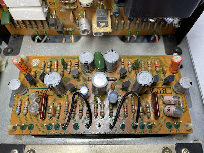
Control Amplifier Board (AWG-027-0)
The control amplifier board in Pioneer SX-1010 is impossible to service without removing it from the chassis. To do it one should remove the front panel, unscrew 6 screws from the sub-chassis and finally remove the shield cover.
This board has six coupling capacitors (C1, C2, C13, C14, C47, C48), four low leakage e-caps (C23, C24, C39, C40) and eighteen aluminum electrolytic capacitors (C7, C8, C15, C16, C25, C26, C29, C30, C31, C32, C41, C42, C45, C46, C49, C50, C51, C52). Also, the additional filtering aluminum e-cap (47uF/25V) is soldered between resistor R61 and ground (pin 2) in the left channel, and between resistor R62 and ground (pin 11) in the right channel. All coupling capacitors are the notorious sky blue Sanyo e-caps. These e-caps become very leaky over time and eventually fail. They should be always replaced with no questions. The coupling capacitors C1 and C 2 were replaced with high-quality film polyester WIMA MKS2 caps. The other four coupling capacitors (C13, C14, C47, C48) and original low leakage e-caps (C23, C24, C39, C40) were replaced with modern low leakage Nichicon UKL caps. The remaining aluminum e-caps were replaced with low impedance Nichicon UPW/UPM caps.
Test results on original capacitors removed from control amplifier board:
C1: rated capacitance – 0.33uF, measured – 0.42uF, ESR – N/A, deviation: +27%
C2: rated capacitance – 0.33uF, measured – 0.46uF, ESR – N/A, deviation: +39%
C7: rated capacitance – 100uF, measured – 109uF, ESR – 0.3Ω, deviation: +9%
C8: rated capacitance – 100uF, measured – 112uF, ESR – 0.3Ω, deviation: +12%
C13: rated capacitance – 2.2uF, measured – 2.8uF, ESR – 3.4Ω, deviation: +27%
C14: rated capacitance – 2.2uF, measured – 2.2uF, ESR – 5.4Ω, deviation: 0%
C15: rated capacitance – 4.7uF, measured – 6.0uF, ESR – 1.1Ω, deviation: +28%
C16: rated capacitance – 4.7uF, measured – 6.3uF, ESR – 1.1Ω, deviation: +34%
C23: rated capacitance – 4.7uF, measured – 4.4uF, ESR – 4.3Ω, deviation: -6%
C24: rated capacitance – 4.7uF, measured – 5.1uF, ESR – 3.2Ω, deviation: +9%
C25: rated capacitance – 10uF, measured – 11uF, ESR – 0.9Ω, deviation: +10%
C26: rated capacitance – 10uF, measured – 12uF, ESR – 0.7Ω, deviation: +20%
C29: rated capacitance – 100uF, measured – 115uF, ESR – 0.2Ω, deviation: +15%
C30: rated capacitance – 100uF, measured – 111uF, ESR – 0.3Ω, deviation: +11%
C31: rated capacitance – 4.7uF, measured – 6.3uF, ESR – 1.2Ω, deviation: +34%
C32: rated capacitance – 4.7uF, measured – 6.1uF, ESR – 1.1Ω, deviation: +30%
C39: rated capacitance – 4.7uF, measured – 4.8uF, ESR – 5.1Ω, deviation: +2%
C40: rated capacitance – 4.7uF, measured – 4.4uF, ESR – 3.1Ω, deviation: -6%
C41: rated capacitance – 10uF, measured – 12uF, ESR – 0.7Ω, deviation: +20%
C42: rated capacitance – 10uF, measured – 11uF, ESR – 0.7Ω, deviation: +10%
C45: rated capacitance – 100uF, measured – 113uF, ESR – 0.3Ω, deviation: +13%
C46: rated capacitance – 100uF, measured – 111uF, ESR – 0.2Ω, deviation: +11%
C47: rated capacitance – 2.2uF, measured – 2.7uF, ESR – 5.2Ω, deviation: +23%
C48: rated capacitance – 2.2uF, measured – 2.8uF, ESR – 3.4Ω, deviation: +27%
C49: rated capacitance – 47uF, measured – 51uF, ESR – 0.3Ω, deviation: +9%
C50: rated capacitance – 47uF, measured – 54uF, ESR – 0.3Ω, deviation: +15%
C51: rated capacitance – 47uF, measured – 53uF, ESR – 0.3Ω, deviation: +13%
C52: rated capacitance – 47uF, measured – 52uF, ESR – 0.4Ω, deviation: +11%
CX1: rated capacitance – 47uF, measured – 55uF, ESR – 0.2Ω, deviation: +17%
CX2: rated capacitance – 47uF, measured – 51uF, ESR – 0.2Ω, deviation: +9%
Two original PNP transistors (Q1 and Q2) installed on this board are 2SA725. These transistors are known to become very noisy over time. I replaced them with modern low noise Fairchild KSA992. Watch the pinout on replacement transistors. The original transistor is BCE and the new one is ECB.
The original NPN transistors (Q3 thru Q8) are 2SC1312. These are also known as noisy/leaky transistors. I replaced them with modern low noise Fairchild KSA1845. Watch the pinout on replacement transistors. The original transistor is BCE and the new one is ECB.
All controls were cleaned with DeoxIT 5% contact cleaner and lubricated with DeoxIT FaderLube 5% spray.
Control amplifier board - before and after
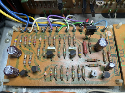
Protection Unit Board (AWM-062-0)
The protection unit has two coupling capacitors (C1, C2) and four aluminum electrolytic capacitors (C3 thru C6). The coupling capacitors are the notorious sky blue Sanyo e-caps. I replaced them with high-quality film polyester Kemet caps. The remaining aluminum e-caps were replaced with low impedance Nichicon UPW caps.
Test results on original capacitors removed from protection unit board:
C1: rated capacitance – 0.22uF, measured – 0.26uF, ESR – N/A, deviation: +18%
C2: rated capacitance – 0.22uF, measured – 0.31uF, ESR – N/A, deviation: +41%
C3: rated capacitance – 330uF, measured – 431uF, ESR – 0.06Ω, deviation: +31%
C4: rated capacitance – 330uF, measured – 427uF, ESR – 0.06Ω, deviation: +29%
C5: rated capacitance – 4.7uF, measured – 5.7uF, ESR – 1.3Ω, deviation: +21%
C6: rated capacitance – 100uF, measured – 138uF, ESR – 0.12Ω, deviation: +38%
The relay driver transistor Q7 suffers from the current spike every time the relay turns off. Eventually, it fails due to severe degradation. I replaced the original 2SC1384 transistor installed in this position with a new Fairchild KSC2690. Also, a fly-back safety diode (1N4004G) was added to the circuit to prevent potential output damage. The safety diode was soldered between pins 9 (anode, "+") and 10 (cathode, "-").
Protection unit - before and after
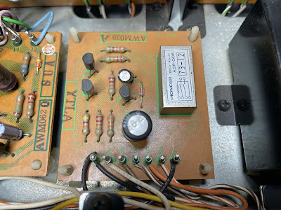
Muting Unit Board (AWM-039-A)
The muting unit has only two aluminum electrolytic capacitors: C1 and C2. I replaced the e-cap C1 with a film polyester WIMA MKS2 cap and e-cap C2 with a low impedance Nichicon UPW cap.
Test results on original capacitors removed from muting unit board:
C1: rated capacitance – 0.47uF, measured – 0.57uF, ESR – N/A, deviation: +21%
C2: rated capacitance – 47uF, measured – 48uF, ESR – 0.14Ω, deviation: +2%
The relay driver transistor Q3 installed on this board is 2SC1318. This transistor is on my prone to failure list, and I replaced it with a modern Fairchild KSC2383. The original and new transistors have the same pinout.
Muting unit - before and after
Equalizer Amplifier Board (AWF-013-0)
The equalizer amplifier (AWF-013-0) is a three-stage differential direct-coupled amplifier. The stability of the equalizer is maximized by a first-stage differential amplifier with 100% DC negative feedback. As a result, the distortion is very low over a wide frequency range from 20Hz to 20kHz. A plus-minus split power supply maintains precisely zero potential at its input and output points.
The equalizer amplifier board (AWF-013-0) has two coupling capacitors (C1, C2) installed in the input signal path, two low leakage e-caps (C11, C12) installed in the output signal path, and seven aluminum e-caps (C5, C6, C9, C10, C19, C20, C21). The original coupling capacitors are the notorious sky blue Sanyo e-caps and I replaced them with modern low leakage Nichicon UKL caps. The original low leakage e-caps installed in the output signal path were also replaced with Nichicon UKL caps.
There is a discrepancy between the service manual and the original capacitors installed on this board. According to the service manual, the seven remaining e-caps (C5, C6, C9, C10, C19, C20, C21) are supposed to be low leakage capacitors (CEANL part number in the manual). However, all of them are ordinary aluminum electrolytic capacitors (CEA part number). I decided to stick with the service manual and replace all of them with low leakage Nichicon UKL caps. It will lower the circuit's noise floor, which is very important for the phono stage.
Test results on original capacitors removed from equalizer amplifier board:
C1: rated capacitance – 2.2uF, measured – 2.4uF, ESR – 3.0Ω, deviation: +9%
C2: rated capacitance – 2.2uF, measured – 2.5uF, ESR – 3.0Ω, deviation: +14%
C5: rated capacitance – 470uF, measured – 582uF, ESR – 0.01Ω, deviation: +24%
C6: rated capacitance – 470uF, measured – 585uF, ESR – 0.04Ω, deviation: +25%
C9: rated capacitance – 100uF, measured – 119uF, ESR – 0.46Ω, deviation: +19%
C10: rated capacitance – 100uF, measured – 115uF, ESR – 0.61Ω, deviation: +15%
C11: rated capacitance – 10uF, measured – 12uF, ESR – 1.3Ω, deviation: +20%
C12: rated capacitance – 10uF, measured – 13uF, ESR – 0.76Ω, deviation: +30%
C19: rated capacitance – 100uF, measured – 107uF, ESR – 0.12Ω, deviation: +7%
C20: rated capacitance – 100uF, measured – 111uF, ESR – 0.32Ω, deviation: +11%
C21: rated capacitance – 220uF, measured – 252uF, ESR – 0.04Ω, deviation: +15%
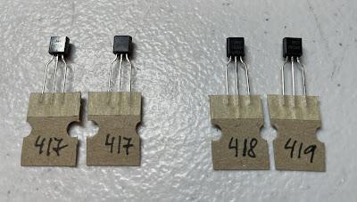
The first stage of the equalizer amplifier is a differential amplifier consisting of two amplifying transistors with a common emitter: Q1/Q3 (left channel) and Q2/Q4 (right channel). The original PNP transistors installed in these positions are 2SA763P. This transistor is not on my prone to failure transistors list but it is often found bad. I decided to replace all 2SA763P transistors as a part of "preventive maintenance". And it was a smart decision! The original transistors were unsoldered from the board and tested with Atlas DCA55 semiconductor analyzer. All four revealed a relatively low current gain. According to the service manual, the 2SA763P transistor installed in the differential pair should have a rank of 5 or 6. Based on the transistor datasheet the current gain for rank 5 is from 250 to 500, and for rank 6 is from 400 to 800. All original 2SA763P transistors on this board have rank 5 but the current gain is below 250 on two transistors (Q1 and Q4, see the testing data below). In addition, each pair of transistors were not well matched. Transistor matching is very important in a differential pair amplifier for normal operating. So, I replaced these transistors with modern low-noise Fairchild KSA992. Before installation, each pair of KSA992 transistors was carefully matched by current gain and base-emitter voltage. Below are test results on four original transistors removed from the board along with test results on four new closely matched transistors. As one can see each pair of original transistors is poorly matched by current gain.
Test results on original transistors 2SA763P:
Left channel: Q1 (gain - 173, Vbe - 0.756V), Q3 (gain - 278, Vbe - 0.752V)
Right channel: Q2 (gain - 283, Vbe - 0.779V), Q4 (gain - 226, Vbe - 0.754V)
Test results on new closely matched transistors KSA992:
Left channel: Q1 (gain - 417, Vbe - 0.759V), Q3 (gain - 417, Vbe - 0.760V)
Right channel: Q2 (gain - 418, Vbe - 0.761V), Q4 (gain - 419, Vbe - 0.760V)
Each pair of KSA992 transistors was carefully matched by current gain and base-emitter voltage
The original NPN transistors (Q5 thru Q8) installed on this board are 2SC1313. These are also known as noisy/leaky transistors. I replaced them with modern low noise Fairchild KSA1845. Watch the pinout on replacement transistors. The original transistor is BCE and the new one is ECB.
Equalizer amplifier board - before and after
Power Amplifier Board (AWH-032-0)
Two power amplifier boards (AWH-032-0) are the most problematic boards to work on in Pioneer SX-1010. Each board is vertically mounted on the chassis and sits very close to the heat sink. The spacing between the PCB and mounting metal plate is too small for servicing. So, I disassembled the power amplifier board from the mounting plate and also moved the heat sink to get a space for servicing.
Mounting plate and heat sink removed for servicing
The power amplifier board (AWH-032-0) has two coupling capacitors (C1, C2) installed in the signal path and two aluminum electrolytic capacitors (C4, C8). The original coupling capacitors are the notorious sky blue Sanyo e-caps. I replaced them with high-quality film polyester WIMA MKS2 caps to improve the signal-to-noise ratio. The remaining aluminum e-caps were replaced with low impedance Nichicon UPW caps.
Test results on original capacitors removed from power amplifier board:
Left channel:
C1: rated capacitance – 0.68uF, measured – 0.75uF, ESR – N/A, deviation: +10%
C2: rated capacitance – 1.5uF, measured – 1.4uF, ESR – 3.5Ω, deviation: -7%
C4: rated capacitance – 10uF, measured – 12uF, ESR – 1.48Ω, deviation: +20%
C8: rated capacitance – 330uF, measured – 411uF, ESR – 0.04Ω, deviation: +25%
Right channel:
C1: rated capacitance – 0.68uF, measured – 0.88uF, ESR – N/A, deviation: +29%
C2: rated capacitance – 1.5uF, measured – 1.8uF, ESR – 5.8Ω, deviation: +20%
C4: rated capacitance – 10uF, measured – 11uF, ESR – 1.08Ω, deviation: +10%
C8: rated capacitance – 330uF, measured – 377uF, ESR – 0.06Ω, deviation: +14%
The power amplifier circuit in Pioneer SX-1010 is a 2-stage differential amplifier and 3-stage Darlington parallel push-pull direct-coupled OCL circuitry. A well-designed differential stage plays a key role in getting low distortion. Carefully matched transistors help maintain precise thermal tracking for low distortion despite changing ambient temperature conditions.
Three PNP transistors (Q1, Q2, Q3) installed on this board are notorious 2SA726 transistors. These transistors get very noisy over time. I replaced them with modern low noise Fairchild KSA992 transistors. Before installation, all new transistors were carefully matched by current gain and base-emitter voltage. Watch the pinout on replacement transistors. The original transistor is BCE and the new one is ECB.
I also replaced two NPN transistors (Q5, Q6) on this board. The original transistors installed in these positions are notorious 2SC1451 and often found faulty. I replaced them with modern Fairchild KSC3503's.
The original trimming resistors VR01 (2.2 kΩ) and VR02 (470 Ω) were replaced with new Bourns potentiometers.
Power amplifier board (left and right channel) - before servicing (sorry, forgot to take a picture of the right channel board before servicing)
Filter Capacitors
I performed an in-circuit test on two large filter capacitors with Atlas ESR70 capacitance meter. Both caps are still within the factory capacitance tolerance and have zero ESR. So, I didn't change them. In general, the filter capacitors rarely fail in vintage gears, and I usually don't replace them unless their ESR is high.
In-circuit test on two filter capacitors - both are still in spec
C9: rated capacitance – 18000uF, measured – 19980uF, ESR – 0Ω, deviation: +11%
C10: rated capacitance – 18000uF, measured – 20510uF, ESR – 0Ω, deviation: +14%
Dial and Meter Lamps
It is pretty easy to replace the meter and dial lamps in the SX-1010. The meter lamps are located under a lamp holder (ANG-097-0). Just unscrew two small screws and this holder will be released from the chassis. I replaced the original incandescent lamps with new warm white LED lamps. Six dial lamps are located on the lamp board assembly AWX-069-0. This board can be easily released from the chassis if unscrewing two small screws from the PC board cover (ANG-100-0). All original incandescent lamps were replaced with warm white LED lamps to maintain the original look and decrease heat. The original electrolytic capacitor C1 (220uF/16V) installed on this board was replaced with a low impedance Nichicon UPW cap.
Lamp board assembly AWX-069-0 - original incandescent lamps
Lamp board assembly AWX-069-0 - warm white LED lamps
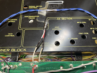
Pilot Lamp for FM Program Source
The original pilot lamp (8V/50mA) for the FM program source was burned out and I replaced it with a new incandescent lamp (8V/60mA). It is very easy to do when the dial scale is removed.
New incandescent pilot lamp for FM program source
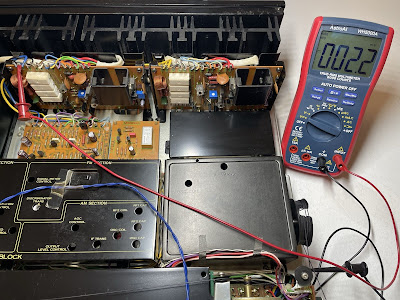
DC offset and Bias Adjustments
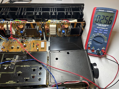
The DC offset and bias adjustments are pretty straightforward and clearly described in the service manual. The DC offset is measured between pin #19 and the ground. I adjusted it as close to zero volts as possible with the trimming resistor VR01 (2.2 kΩ). The bias is measured across two emitter resistors (R29 and R30) between pins #14 and #16. Be aware that there is an error in the service manual. The bias should be adjusted to 25mV instead of 50mV (as stated in the manual). It corresponds to the idling current of 25mA. So, I adjusted the bias on each channel to ~25mA with the trimming resistor VR02 (470 Ω).
DC offset on the left and right channel after restoration
Bias on the left and right channel after restoration
Output Power Test
The final output power test was performed at the end of my restoration. The amplifier was loaded with a low inductance 8Ω/100W dummy resistor for each channel. The oscilloscope was connected across the speaker terminals and a sine-wave signal of 1kHz was applied to the AUX jacks. The output sine-wave signal was perfectly symmetrical on both channels with no clipping up to 28.10 VRMS (left channel) and 28.02 VRMS (right channel). It corresponds to the output power of 98.7W on the left channel and 98.1W on the right channel. Yes, it is still a real Monster! Even though this unit is 48 years old.
Output power test
As usual, all the knobs and the front panel were gently cleaned in warm water with dish soap. All knobs were also slightly polished by Mothers Mag & Aluminum polish to remove some small spots of aluminum oxidation. All pots and switches have been cleaned with DeoxIT 5% contact cleaner and lubricated with DeoxIT FaderLube 5% spray.
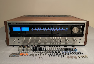
The final result can be seen in the photos below. The receiver looks brand new again and sounds fantastic! Please watch a short demo video at the end of this post. Thank you for reading.
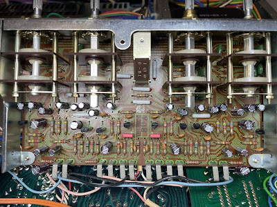
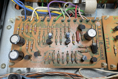
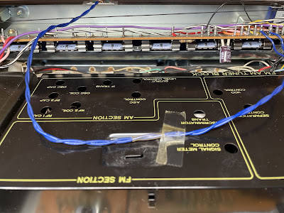
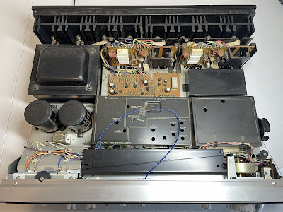
Pioneer SX-1010 - look inside before restoration













A very detailed and complet report of the restoration. Just now in that times i'm working at my brothers SX1010. I'm not so perfectly equipped as you and my knowledge is rather poor. Therfore your report is a great help for me.
ReplyDeleteA big thank you
Josef
tyvm for your work, it helps eminsely for those trying to diy, throu your and other technition's help, have started to revive units in the simmilar or same manner
ReplyDeleteHi, you did a pretty good job, I've stumbled on your website by luck, Nice to see someone who takes restoration on a new level. I also use the same transistors to replace these old ones who are, like you said, often noisy and mismatched. The fairchilds aren't available at digi-key but I used ON semi and they do the job fine.
ReplyDeleteI have to buy myself a component analyser because mine isn't reliable anymore. Do you suggest the same as yours or another one?
I've did pretty much the same job for a friend of mine as I'm an electronic technician since the early 90s, it was a SX-838, and I have a SX-1010 to get done. The one I have worked on has 3 noisy transistors on the tone control board, and I did the same thing as you did, replaced them with modern equivalent and got rid of the tantalum capacitors and replaced them with Nichicon UPW serie.
It also had a strange trouble on the tuner board, the low pass filter was replaced at some point and they broke the pcb track so I put a jumper. Nice job overall. I like to work on these older receiver.
Very well written summary BTW, very interesting, thanks you.