Unit: AM/FM Stereo Receiver
Manufacturer: Pioneer
Model: SX-770
SN: RL3311218
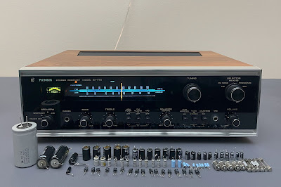
I bought this receiver a few months ago from a kind old gentleman for a fair price. The receiver is in excellent cosmetic condition and I always wanted to have this model in my private collection.
The SX-770 was introduced in 1970 just before the silver face era and was manufactured in 1970-71. It produces 15 watts per channel into 8 ohms with no more than 0.8% total harmonic distortion. The list price in 1970 was $249.95 (Ref. High Fidelity Magazine, April 1970, page 33).
As Pioneer states in its brochure: "The SX-770 has a uniquely attractive smoked dial glass. AM and FM indicators light up only during the reception, and the tuning needle glides over a tuning scale illuminated in blue. With its oiled walnut cabinet and black front panel, the SX-770 makes a handsome addition to the décor of any room". And I totally agree with that! It has a fantastic design, clear and warm sound, and a so-called "McIntosh look". I think it is a very cool receiver from the early 70's.
According to the Pioneer database, this particular unit was manufactured in December 1971. So, it was exactly 50 years ago!
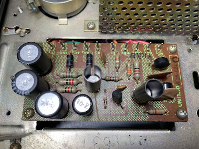
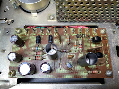
Power Supply Board (W16-024)
The power supply board (W16-024) has four aluminum electrolytic capacitors C4 thru C7. I replaced them with low impedance and high-reliability Nichicon UPW/UPM caps. All original e-caps removed from this board were tested with Atlas ESR70 capacitance meter and the results are below. All of them are outside the factory capacitance tolerance +/- 20%.
Test results on original capacitors removed from the power supply board:
C4: rated capacitance – 100uF, measured – 128uF, ESR – 0.08Ω, deviation: +28%
C5: rated capacitance – 220uF, measured – 297uF, ESR – 0.01Ω, deviation: +35%
C6: rated capacitance – 220uF, measured – 288uF, ESR – 0.01Ω, deviation: +31%
C7: rated capacitance – 100uF, measured – 151uF, ESR – 0.26Ω, deviation: +51%
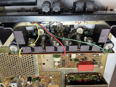
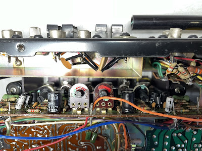
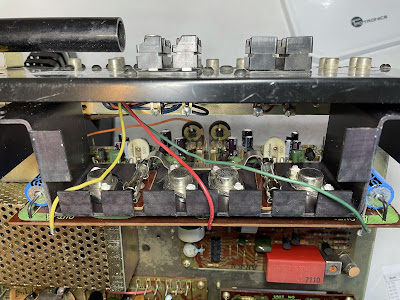
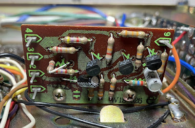
The NPN transistor Q2 installed on this board is 2SC870. This is a well-known transistor prone to failure. I replaced it with a modern low noise Fairchild KSC1845. Watch the pinout on the replacement transistor. The original transistor (2SC870) is BCE and the new one (KSC1845) is ECB.
Power supply board - before and after
Control Amplifier Board (W15-033)
Four original coupling capacitors (C1, C2, C7, C8) installed in the signal path on this board are failure-prone sky blue Sanyo e-caps. As expected, the measured capacitance of all e-caps is outside of the factory capacitance tolerance. The coupling capacitor C8 is still within the factory tolerance but its ESR is abnormally high. For more information about sky blue Sanyo e-caps refer to my previous post on Pioneer SX-828 restoration. Two e-caps installed in the input signal path (C1, C2) were replaced with film polyester WIMA MKS2 caps. And other two e-caps installed in the output signal path (C7, C8) were replaced with modern low leakage Nichicon UKL capacitors. The measured capacitance of the remaining four aluminum e-caps are also outside of the factory capacitance tolerance and I replaced them with low impedance Nichicon UPW/UPM caps.
Test results on original capacitors removed from the control amplifier board:
C1: rated capacitance – 0.47uF, measured – 0.61uF, ESR – N/A, deviation: +30%
C2: rated capacitance – 0.47uF, measured – 0.79uF, ESR – N/A, deviation: +68%
C5: rated capacitance – 100uF, measured – 139uF, ESR – 5.9Ω, deviation: +39%
C6: rated capacitance – 100uF, measured – 153uF, ESR – 0.84Ω, deviation: +53%
C7: rated capacitance – 2.2uF, measured – 2.7uF, ESR – 2.8Ω, deviation: +23%
C8: rated capacitance – 2.2uF, measured – 2.1uF, ESR – 13.6Ω, deviation: -5%
C17: rated capacitance – 47uF, measured – 66uF, ESR – 0.24Ω, deviation: +40%
C18: rated capacitance – 47uF, measured – 65uF, ESR – 0.21Ω, deviation: +38%
Two NPN transistors installed on this board are 2SC870 (Q1, Q2) and I replaced them with a modern low noise Fairchild KSC1845.
TREBLE and BASS control potentiometers were cleaned and lubricated with DeoxIT FaderLube 5% spray.
Control amplifier board - before and after
Push Switch Unit B (W15-087)
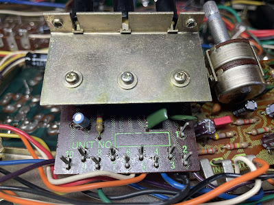
There is only one electrolytic capacitor C13 on this board. The original e-cap installed in this position is a notorious sky blue Sanyo e-cap. I replaced it with a film polyester WIMA MKS2 cap.
Test results on original capacitors removed from the push switch unit B:
C13: rated capacitance – 0.47uF, measured – 0.58uF, ESR – N/A, deviation: +23%
A small metal mounting plate covers three push switches and limits access to the openings for cleaning and lubricating. Fortunately, this plate can be easily removed to get better access to these switches.
Push switch unit B - before and after
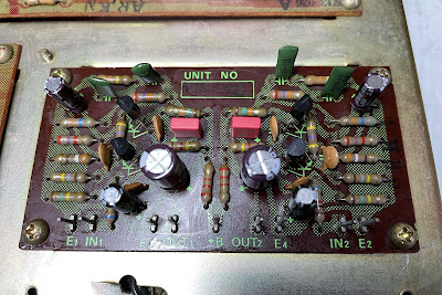
Head Amplifier Board (W15-032)
The head amplifier board has eight aluminum electrolytic capacitors: C1, C2, C7, C8, C9, C10, C15, and C16. Four of them are installed in the signal path. The original e-caps C1 and C2 installed in the input signal path are just ordinary aluminum e-caps. I replaced them with modern low leakage Nichicon UKL capacitors to improve a signal-to-noise ratio. The original e-caps C7 and C8 installed in the output signal path are notorious sky blue Sanyo e-caps. These were replaced with high-quality film polyester WIMA MKS2 caps. The remaining four aluminum e-caps were replaced with low impedance Nichicon UPW caps.
Test results on original capacitors removed from the head amplifier board:
C1: rated capacitance – 10uF, measured – 13uF, ESR – 3.2Ω, deviation: +30%
C2: rated capacitance – 10uF, measured – 13uF, ESR – 4.1Ω, deviation: +30%
C7: rated capacitance – 0.47uF, measured – 0.59uF, ESR – N/A, deviation: +26%
C8: rated capacitance – 0.47uF, measured – 0.61uF, ESR – N/A, deviation: +30%
C9: rated capacitance – 33uF, measured – 48uF, ESR – 1.1Ω, deviation: +46%
C10: rated capacitance – 33uF, measured – 47uF, ESR – 1.2Ω, deviation: +42%
C15: rated capacitance – 100uF, measured – 119uF, ESR – 0.01Ω, deviation: +19%
C16: rated capacitance – 100uF, measured – 163uF, ESR – 0.01Ω, deviation: +63%
Four NPN transistors installed on this board are 2SC871 (Q1, Q2) and 2SC870 (Q3, Q4). Both of them are well-known transistors prone to failure. I replaced them with a modern low-noise Fairchild KSC1845. Before installation, the new transistors were carefully matched by current gain and base-emitter voltage. Pay attention to the current gain in KSC1845 transistors while selecting them for replacement. The minimum current gain of the 2SC870 transistor is 250 whereas the 2SC871 has a minimum current gain of 350. So, make sure that both KSC1845 transistors installed in Q1 and Q2 positions have a current gain of at least 350 or higher. Also, watch the pinout on replacement transistors. The original 2SC870/871 transistor is BCE and the new one (KSC1845) is ECB.
Head amplifier board - before and after
Main Amplifier Board (W15-085)
The main amplifier board has twelve radial electrolytic capacitors C1 thru C8, C11 thru C14, and two axial coupling capacitors C17, C18. The original e-caps C3, C4, C5, C6 installed in the signal path are just ordinary aluminum e-caps. I replaced them with modern low leakage Nichicon UKL capacitors to improve a signal-to-noise ratio. The original axial coupling capacitors C17 and C18 installed in the output signal path were replaced with new Vishay axial e-caps (021 ASM series). The remaining eight aluminum e-caps were replaced with low impedance Nichicon UPW caps.
Test results on original capacitors removed from the main amplifier board:
C1: rated capacitance – 100uF, measured – 139uF, ESR – 0.31Ω, deviation: +39%
C2: rated capacitance – 100uF, measured – 156uF, ESR – 0.24Ω, deviation: +56%
C3: rated capacitance – 10uF, measured – 12uF, ESR – 3.1Ω, deviation: +20%
C4: rated capacitance – 10uF, measured – 12uF, ESR – 2.2Ω, deviation: +20%
C5: rated capacitance – 22uF, measured – 27uF, ESR – 0.65Ω, deviation: +23%
C6: rated capacitance – 22uF, measured – 27uF, ESR – 0.75Ω, deviation: +23%
C7: rated capacitance – 47uF, measured – 65uF, ESR – 0.97Ω, deviation: +38%
C8: rated capacitance – 47uF, measured – 63uF, ESR – 0.92Ω, deviation: +34%
C11: rated capacitance – 47uF, measured – 64uF, ESR – 0.91Ω, deviation: +36%
C12: rated capacitance – 47uF, measured – 63uF, ESR – 1.24Ω, deviation: +34%
C13: rated capacitance – 100uF, measured – 144uF, ESR – 0.18Ω, deviation: +44%
C14: rated capacitance – 100uF, measured – 149uF, ESR – 0.18Ω, deviation: +49%
C17: rated capacitance – 1000uF, measured – 1422uF, ESR – 0.01Ω, deviation: +42%
C18: rated capacitance – 1000uF, measured – 1270uF, ESR – 0.01Ω, deviation: +27%
Two NPN transistors (Q1, Q2) installed on this board are 2SC870 and I replaced them with low noise Fairchild KSC1845's.
It's hard to take a good picture of this board because it couldn't be completely released from the chassis. Some wires soldered to the board are very short. This board is still pretty convenient to service but just with limited access.
Main amplifier board - before and after
Muting Unit (W18-026)
The muting unit has two electrolytic capacitors C1 and C2. The e-cap C2 installed in the signal path was replaced with a low leakage Nichicon UKL capacitor. The e-cap C1 was replaced with a low impedance Nichicon UPW cap.
Test results on original capacitors removed from the muting unit:
C1: rated capacitance – 4.7uF, measured – 6.5uF, ESR – 2.6Ω, deviation: +38%
C2: rated capacitance – 2.2uF, measured – 3.7uF, ESR – 2.5Ω, deviation: +68%
Three NPN transistors (Q1, Q2, Q3) installed on this board are 2SC870. These were replaced with low noise Fairchild KSC1845's.
Muting unit - before and after
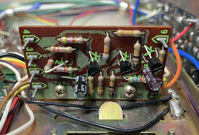
MPX Unit (W13-026A)
There are at least two different versions of the MPX circuit in the Pioneer SX-770: W13-024 and W13-026. This particular unit has version W13-026A. Five electrolytic capacitors are installed on this board: C1, C2, C4, C8, and C9. The e-cap C1 installed in the signal path was replaced with a low leakage Nichicon UKL capacitor. Two e-caps C8 and C9 installed in the signal path before the low pass filter are notorious sky blue Sanyo e-caps. These were replaced with film polyester WIMA MKS2 caps. The remaining e-caps were replaced with low impedance Nichicon UPW caps.
Test results on original capacitors removed from the MPX unit:
C1: rated capacitance – 2.2uF, measured – 3.3uF, ESR – 2.8Ω, deviation: +50%
C2: rated capacitance – 10uF, measured – 12uF, ESR – 3.1Ω, deviation: +20%
C4: rated capacitance – 3.3uF, measured – 4.6uF, ESR – 2.6Ω, deviation: +39%
C8: rated capacitance – 0.47uF, measured – 0.55uF, ESR – N/A, deviation: +17%
C9: rated capacitance – 0.47uF, measured – 0.57uF, ESR – N/A, deviation: +21%
The NPN transistor installed in position Q1 is the notorious 2SC870. I replaced it with a modern low noise Fairchild KSC1845 transistor. The other four NPN transistors (Q2, Q3, Q4, and Q5) installed on this board are prone to fail 2SC711. These were also replaced with a modern low noise Fairchild KSC1845 transistor.
MPX unit - before and after
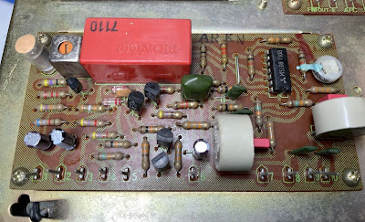
Tuner Unit (W31-002)
The tuner unit has six aluminum electrolytic capacitors: C8, C19, C30, C32, C33, and C35. One of them (C33) is a notorious sky blue Sanyo e-cap. I replaced it with a film polyester WIMA cap. The e-cap C30 installed in the signal path was also replaced with a WIMA cap. The remaining aluminum capacitors were replaced with low impedance Nichicon UPW caps.
Test results on original capacitors removed from the tuner unit:
C8: rated capacitance – 10uF, measured – 13uF, ESR – 3.3Ω, deviation: +30%
C19: rated capacitance – 4.7uF, measured – 5.5uF, ESR – 3.4Ω, deviation: +17%
C30: rated capacitance – 0.47uF, measured – 0.53uF, ESR – N/A, deviation: +13%
C32: rated capacitance – 4.7uF, measured – 5.4uF, ESR – 3.4Ω, deviation: +15%
C33: rated capacitance – 1uF, measured – 1.2uF, ESR – 2.2Ω, deviation: +20%
C35: rated capacitance – 100uF, measured – 142uF, ESR – 0.32Ω, deviation: +42%
Tuner unit - before and after
Off-Board Parts
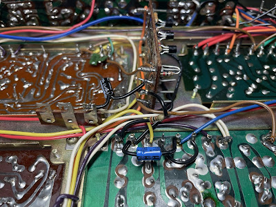
The original axial electrolytic capacitor C12 (220uF/6.3V) installed across the signal meter leads was replaced with a new Vishay axial e-cap (021 ASM series).
The original axial electrolytic capacitor C21 (4.7uF/16V) installed between the muting & MPX units was replaced with a low leakage Nichicon UKL capacitor. Note that even though the original e-cap is still within the factory capacitance tolerance the measured ESR is very high (see test data below).
The filter capacitor C15 (3300uF/50V) was tested in-circuit with Atlas ESR70 capacitance meter. It is still within the factory capacitance tolerance and has almost zero ESR. But I decided to replace it anyway with a new Nichicon LKG e-cap (3300uF/63V) as a part of preventive maintenance. The new Nichicon LKG e-cap is the same diameter as the original one but shorter. Thus, the same clamp can be used to attach it to the chassis.
Test results on original capacitors C12, C15, and C21:
C12: rated capacitance – 220uF, measured – 304uF, ESR – 0.24Ω, deviation: +38%
C15: rated capacitance – 3300uF, measured – 3890uF, ESR – 0.01Ω, deviation: +18%
C21: rated capacitance – 4.7uF, measured – 5.5uF, ESR – 12.8Ω, deviation: +17%
Original and new e-caps C21 and C12
Original and new filter capacitor C15
Dial and Program Indicator Lamps
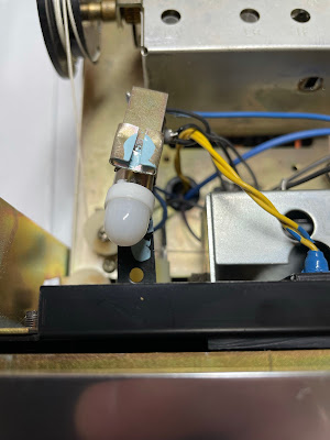
Four program indicator lamps in the Pioneer SX-770 are Bayonet base lamps (8V, 150mA). I replaced them with new incandescent lamps. The original tuning meter lamp is also a Bayonet base lamp. This lamp is mounted very close to the plastic tuning meter and over time discolors it due to extensive heat. I replaced it with a warm white LED lamp. The LED lamp has a similar color temperature as the original incandescent lamp but produces much less heat. This will protect the plastic from discoloration.
Warm white LED lamp behind the tuning meter
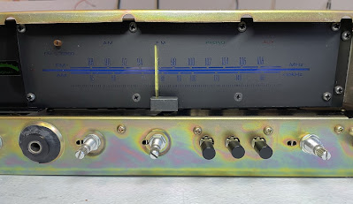
To replace four dial lamps in the SX-770 the front panel and dial scale should be removed. It is actually very easy to do in comparison to most Marantz receivers from the 70's. The dial scale is mounted on the chassis with eight screws. I replaced the original incandescent lamps with warm white LED lamps.
Original dial lamps - easy to replace
Audio Adjustments
The service manual has no instructions for main amplifier adjustment. I used the following procedure to adjust the amplifier.
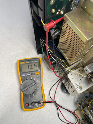
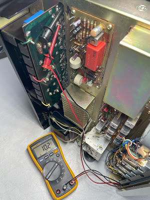
First of all, I checked the voltage at pin +B1 on the main amplifier board. The measured voltage was 46.10V. Then I set the collector voltage of transistor Q11 to half of the voltage measured at pin +B1 with trimming resistor VR1. Similarly, the collector voltage of transistor Q12 was set to half of the voltage measured at pin +B1 with trimming resistor VR2. After that, the oscilloscope was connected across the speaker terminals and a sine-wave signal of 1kHz was applied to the AUX jacks. The audio signal was increased until the audio output on the oscilloscope began to start clipping. The trimming resistor VR1 (VR2) was slightly adjusted for equal clipping on each channel.
The idle current was set to ~20mA in each channel with trimming resistor VR3 (VR4). This current can be set by measuring the voltage drop across emitter resistor R33 (R34). Since the nominal resistance of R33 (R34) is 0.5Ω, the voltage drop should be ~10mV.
Bias on the left and right channels after restoration
Output Power Test
The final output power test was performed at the end of my restoration. The amplifier was loaded with a low inductance 8Ω/100W dummy resistor for each channel. The oscilloscope was connected across the speaker terminals and a sine-wave signal of 1kHz was applied to the AUX jacks. The output sine-wave signal was perfectly symmetrical on both channels with no clipping up to 10.77 VRMS (left channel) and 10.61 VRMS (right channel). It corresponds to the output power of 14.5W on the left channel and 14.1W on the right channel.
Output power test
As usual, all the knobs and the front panel were gently cleaned in warm water with dish soap. All controls have been cleaned with DeoxIT 5% contact cleaner and lubricated with DeoxIT FaderLube 5% spray.
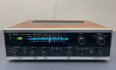
The final result can be seen in the photos below. This receiver has a magnificent look. The sound is beautiful, clear and lovely warm. This is a very underrated receiver from the early 70's. I am very happy to have it in my private collection in excellent cosmetic condition. Please watch a short demo video at the end of this post. Thank you for reading.
Pioneer SX-770 - after restoration








_before%20servicing.jpg)
_after%20servicing.jpg)




love the 770
ReplyDeletesent you a email with a couple questions
Hello. Please tell me the specification of the lamp for ordering. I mean Warm white LED lamp behind the tuning meter.
ReplyDeleteHello Mikhail, you can order the lamp on this website www.wjoe.com. The owner provides the best price and service (no affiliation). The original incandescent lamp (behind the tuning meter) has the following spec: 8V, 0.15A, Bayonet base.
DeleteOleg, thanks a lot!
ReplyDeleteGreat work as usual. Thanks for taking the time to publish your work. It helps us rookies a lot. One question, I see a lot of techs increase uF and voltage in electrolytic caps, especially power supplies. Is this unneeded or harmful?
ReplyDeleteI usually don't change the nominal capacitance and always prefer to stick to the original circuit. The only exception would be filter capacitors. However, you should also be careful with them. It is usually safe to increase the capacitance, for example, from 8000 uF to 10000 uF. But I do not recommend increasing it more than 30% above the rated capacitance, as more surge current can overload or even destroy the rectifiers. But it is always worth increasing the operating voltage for electrolytic capacitors (especially for those installed in the power supply). Many electrolytic capacitors found in power supply boards operate very close to their maximum voltage rating. A good rule of thumb here is that: the maximum voltage rating of the electrolytic capacitor should be above its operating voltage by at least 20%. For example, if the voltage measured across the leads is 50V DC then install a new electrolytic capacitor with a maximum voltage rating of 63V or 80V. Don't install a new capacitor with a maximum voltage rating of 55V.
DeleteThank you. That makes sense on the rectifiers. I will incorporate this info in my next rebuild~
DeleteVery neat job, what would you guess you have in cost of parts invested in this revival? I have the same model , my Dad bought it new.
ReplyDeleteI spent about $50 on parts, but that was a year ago. Spare parts are now more expensive than a year ago.
Deleteare the fuse lamps also 8v 150 ma?
ReplyDeleteThe original incandescent dial lamps are rated at 8V/300mA.
DeleteI have been fascinated by your restorations and learned a lot. In my younger days I used to build basic amps. and photo analyzers. I wasn't sure how to email you so I wanted to ask you if your Pioneer SX 770 might be for sale? I used to own one back in the 70's and have really wanted to find one that's been restored as you have done, with no luck. I am on the east coast and if for sale, would love to have the chance to purchase it for myself and son. In any case, keep up the fine work. Dave
ReplyDeleteHi Dave, This receiver is from my own collection and is not for sale. I have been looking for this model for many years until I found it in perfect cosmetic condition. Usually this model can only be found in fairly poor condition.
Delete