Unit: Stereo Integrated Amplifier
Manufacturer: Pioneer
Model: SA-7500 II
SN: XH36111130
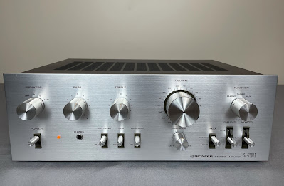
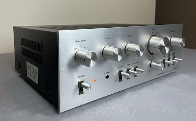
Today I'm showcasing a Pioneer SA-7500 II stereo integrated amplifier that came in for restoration. The SA-7500 II was manufactured from 1975 to 1978. It produces 40 watts per channel into 8 ohms with no more than 0.3% total harmonic distortion. The rear panel of SA-7500 II has input jacks for two turntables, two tape decks, a tuner, and an auxiliary source.
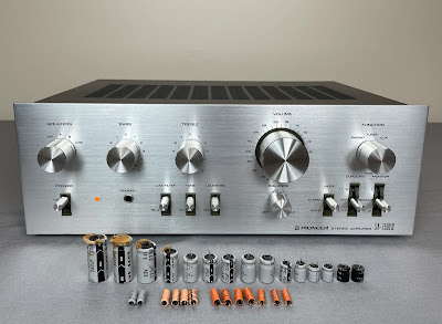
This particular unit is in perfect cosmetic condition and has no issues with electronics. I completed just routine servicing, i.e. cleaning and lubricating all the controls, replacing all electrolytic capacitors, bias adjustment checking, and final output power test. According to the Pioneer database, this particular unit was manufactured in August 1977.
Control Amplifier Board (AWG-047)
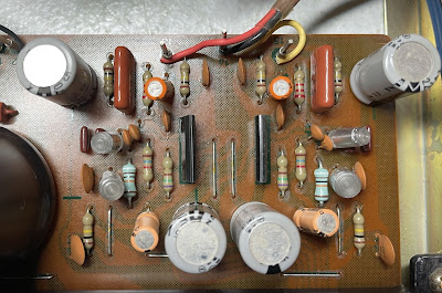
The control amplifier board AWG-047 is mounted to the sub-panel. In general, this board can be serviced without removing it from the chassis. However, two variable resistors (Bass and Treble) are assembled on the board and it is much easier to clean them when the board is being removed. So, I cleaned and lubricated both variable resistors with DeoxIT FaderLube 5% spray. The Volume variable resistor is assembled on its own small board and also mounted to the sub-panel. I cleaned it with DeoxIT FaderLube 5% spray as well. Finally, all the switches were cleaned with DeoxIT 5% contact cleaner and then lubricated with DeoxIT FaderLube 5% spray.
The original low leakage e-caps C5, C6, C9, and C10 installed in the signal path were replaced with modern low leakage Nichicon UKL capacitors. The remaining aluminum e-caps C19 and C20 were replaced with low impedance and high-reliability Nichicon UPW caps. All original e-caps removed from this board were tested with Atlas ESR70 capacitance meter and results are below. All of them except e-cap C5 are outside the factory capacitance tolerance +/- 20%.
Test results on original capacitors removed from the control amplifier board:
C5: rated capacitance – 47uF, measured – 54uF, ESR – 1.49Ω, deviation: +15%
C6: rated capacitance – 47uF, measured – 57uF, ESR – 1.23Ω, deviation: +21%
C9: rated capacitance – 3.3uF, measured – 4.2uF, ESR – 1.14Ω, deviation: +27%
C10: rated capacitance – 3.3uF, measured – 4.3uF, ESR – 1.21Ω, deviation: +30%
C19: rated capacitance – 47uF, measured – 59uF, ESR – 0.05Ω, deviation: +26%
C20: rated capacitance – 47uF, measured – 57uF, ESR – 0.16Ω, deviation: +21%
Control amplifier board (AWG-047) - before and after
AF Amplifier Board (AWK-079)
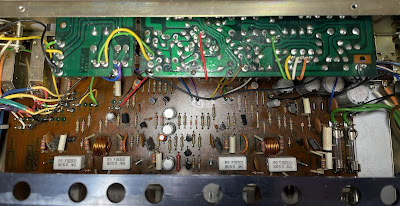
The power supply, protection, phono equalizer, and power amplifier circuits are assembled on one board (AWK-079).
The power supply and protection circuit has 10 aluminum e-caps: C45 thru C48, C54 thru C56, and C58 thru C60. All of them were replaced with low impedance Nichicon UPW/UPM caps.
Test results on original capacitors removed from the power supply and protection circuit:
C45: rated capacitance – 330uF, measured – 372uF, ESR – 0.08Ω, deviation: +13%
C46: rated capacitance – 330uF, measured – 373uF, ESR – 0.08Ω, deviation: +13%
C47: rated capacitance – 100uF, measured – 117uF, ESR – 0.12Ω, deviation: +17%
C48: rated capacitance – 2.2uF, measured – 2.1uF, ESR – 4.9Ω, deviation: -5%
C54: rated capacitance – 330uF, measured – 356uF, ESR – 0.01Ω, deviation: +8%
C55: rated capacitance – 330uF, measured – 344uF, ESR – 0.01Ω, deviation: +4%
C56: rated capacitance – 220uF, measured – 227uF, ESR – 0.02Ω, deviation: +3%
C58: rated capacitance – 47uF, measured – 52uF, ESR – 0.24Ω, deviation: +11%
C59: rated capacitance – 100uF, measured – 107uF, ESR – 0.08Ω, deviation: +7%
C60: rated capacitance – 220uF, measured – 263uF, ESR – 0.01Ω, deviation: +20%
The phono equalizer circuit has four low leakage e-caps installed in the input (C1, C2) and output (C23, C24) signal path, two filtering aluminum e-caps (C61, C62), and two DC blocking aluminum e-caps (C9, C10) in the RIAA feedback loop. The e-caps installed in the input signal path were replaced with high-quality film polyester WIMA MKS2 caps. The e-caps installed in the output signal path were replaced with modern low leakage Nichicon UKL capacitors. Pay attention to the polarity of e-caps C23 and C24 installed in the output signal path. The polarity on the silkscreen is backward! The remaining four aluminum e-caps were replaced with low impedance Nichicon UPW caps.
The polarity of e-caps C23 & C24 is backward on the silkscreen
Test results on original capacitors removed from the phono equalizer circuit:
C1: rated capacitance – 1uF, measured – 1.1uF, ESR – 4.4Ω, deviation: +10%
C2: rated capacitance – 1uF, measured – 1.1uF, ESR – 5.1Ω, deviation: +10%
C9: rated capacitance – 220uF, measured – 264uF, ESR – 0.04Ω, deviation: +20%
C10: rated capacitance – 220uF, measured – 270uF, ESR – 0.05Ω, deviation: +23%
C23: rated capacitance – 2.2uF, measured – 2.8uF, ESR – 2.1Ω, deviation: +27%
C24: rated capacitance – 2.2uF, measured – 2.7uF, ESR – 2.4Ω, deviation: +23%
C61: rated capacitance – 220uF, measured – 265uF, ESR – 0.04Ω, deviation: +21%
C62: rated capacitance – 220uF, measured – 254uF, ESR – 0.06Ω, deviation: +16%
Phono equalizer circuit - before and after
The power amplifier circuit has two low leakage e-caps C31, C32 installed in the signal path, and two aluminum e-caps C35, C36 installed in the negative feedback loop. The e-caps installed in the input path were replaced with modern low leakage Nichicon UKL capacitors. And the remaining two aluminum e-caps were replaced with low impedance Nichicon UPW caps.
Test results on original capacitors removed from the power amplifier circuit:
C31: rated capacitance – 2.2uF, measured – 2.8uF, ESR – 2.1Ω, deviation: +27%
C32: rated capacitance – 2.2uF, measured – 2.7uF, ESR – 2.1Ω, deviation: +23%
C35: rated capacitance – 47uF, measured – 56uF, ESR – 0.74Ω, deviation: +19%
C36: rated capacitance – 47uF, measured – 55uF, ESR – 0.79Ω, deviation: +17%
AF amplifier board (AWK-079) - before and after
Bias Adjustments
The bias in Pioneer SA-7500 II is measured across two emitter resistors R57/R59 on the left channel (terminals TP1 and TP2) and across R58/R60 on the right channel (terminals TP3 and TP4). According to the service manual, the DC voltmeter reading tolerance is from 10mV to 70mV. This model has no trimmers for bias adjustments. Instead, it has one jumper per channel which should be cut if the voltage is less than 10mV. I measured the bias in each channel and the DC voltmeter reading was close to the middle of factory tolerance. So, no jumper leads were cut.
Bias on the left and right channel after restoration
Output Power Test
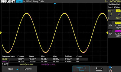
The final output power test was performed at the end of my restoration. The amplifier was loaded with a low inductance 8Ω/100W dummy resistor for each channel. The oscilloscope was connected across the speaker terminals and a sine-wave signal of 1kHz was applied to the AUX jacks. The output sine-wave signal was perfectly symmetrical on both channels with no clipping up to 18.96 VRMS (left channel) and 19.23 VRMS (right channel). It corresponds to the output power of 44.9W on the left channel and 46.2W on the right channel.
Output power test
As usual, all the knobs and the front panel were gently cleaned in warm water with dish soap. All knobs were also slightly polished by Mothers Mag & Aluminum polish to remove some small spots of aluminum oxidation.
The final result can be seen in the photos below. This amplifier looks really very cool: clean and shiny. The sound is rich and very detailed. Please watch a short demo video at the end of this post. Thank you for reading.
Pioneer SA-7500 II - after restoration
Demo video after repair & restoration


