Unit: AM/FM Stereo Receiver
Manufacturer: Marantz
Model: 2238B
SN: U090424
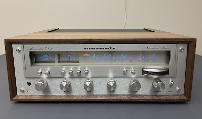
I bought this receiver a few months ago from the original owner for a fair price. The receiver is in perfect cosmetic condition. The faceplate, all knobs, and push buttons are flawless. According to the original owner it has never been serviced. It is certainly worth restoring.
Marantz 2238B was manufactured from 1977 to 1980. It produces 38 watts per channel into 8 ohms with no more than 0.08% total harmonic distortion. The optional walnut veneer cabinet for this model is WC-122.
According to the factory stamp on the chassis, this unit was manufactured in January 1978.
Any successful restoration always begins with a good cleaning. Believe me. It has been proven many times after many successful restorations. So, before the servicing, I carefully vacuumed out this unit inside and cleaned each board. The dust was dry and easily removed with a vacuum cleaner and a set of small brushes. It is always worth cleaning any vintage gear before servicing.
Marantz 2238B - before and after cleaning
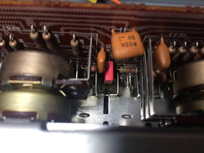
Variable capacitor - after cleaning (extremely important to keep it clean for best AM/FM reception)
Initial Evaluation and Troubleshooting
Despite the almost perfect cosmetic condition, all push switches in this unit were severely oxidized. The VOLUME and BALANCE pots were also rather dirty. All other switches and pots were in good shape. I thoroughly cleaned all pots and switches with DeoxIT 5% contact cleaner and lubricated them with DeoxIT FaderLube 5% spray. This cleaning can be relatively easily performed from the back side of the unit. However, the following quick audio test showed that some switches still suffer from oxidized contacts. Before the second round of cleaning, I decided to perform a square wave test at 100Hz to see which push switch mostly suffers from oxidation. This test is more informative than a sine wave test and also provides information about the low-frequency response of a circuit. So, I connected my function generator to the AUX terminals, applied a square-wave signal of 100Hz, and traced the input signal with my oscilloscope throughout all boards down to the speaker's terminals. The square wave signal had a perfect shape at the input terminals of the tone amplifier board (as expected) but some degree of distortion at the output terminals depending on which push switch was depressed. The distortion was intermittent and occasionally disappeared by itself after the particular push switch was pressed/depressed several times. Often, the push switch changed the shape of the input signal in only one channel. This is a clear sign that some contacts in these push switches are still not clean enough. The test revealed that three particular push switches (TAPE MONITOR, HIGH FILTER, and LOUDNESS) still require additional cleaning with DeoxIT. Eventually, after several more attempts, all contacts were completely cleaned and an almost perfect square wave signal was achieved at the output terminals of the tone amplifier board. Yes, sometimes it is very hard to clean all contacts in these vintage gears from the first attempt. The square wave test helps to make sure that all switches are completely clean and free from oxidation.
The signal at the input terminals of tone amp board (pins JE01 & JE02) - perfect square wave
The signal at the output terminals of the tone amp board (pins JE23 & JE24) - unequal square wave signal between the left and right channel
The signal at the output terminals of the tone amp board (pins JE23 & JE24) - the loudness switch depressed but only the right channel (pink) responded. The left channel (yellow) still has the same square-wave shape.
The signal at the output terminals of the tone amp board (pins JE23 & JE24) - after cleaning, almost a perfect square wave from both channels, with steep leading and falling edges and a flat top.
Tone Amplifier Board (PE01)
The tone amplifier board is the most difficult to service in Marantz 2238B. The board is sandwiched between the front chassis bracket and the tuner board. To pull this board out the front metal bracket should be disassembled from the chassis. It wouldn't be a problem unless the dial stringing was not assembled on the front bracket! Well, this is not the smartest engineering decision because it makes servicing a tone amplifier board extremely difficult. On the other hand, I don't think that Marantz's engineers could even imagine in 1977 that this gear will be still running great in the twenty-first century! Anyway. I had three choices here: leave this board alone and don't service it, remove the front metal bracket and later struggle with dial restringing, or try to find a way to replace the electronic components on this board without disassembling it from the chassis. I examined the tone amplifier board again from both sides and noticed that at least a few e-caps installed close to the edge of this board are accessible for replacement. However, five electrolytic capacitors are hard to access since they are installed in the middle of the tone amplifier board. I decided to challenge myself and try to replace all e-caps on this board without disassembling it the chassis. It was very hard to do and took me at least a few hours to complete. But eventually, I replaced all e-caps on this board and didn't damage any wires or PCB.
Tone amplifier board - challenging to access the electronic components and replace them
The tone amplifier board has six low leakage e-caps CE09/CE10, CE23/CE24, CE25/CE26, two non-polar e-caps CE27/CE28, and three aluminum e-caps CE07/CE08, CE35. I replaced two non-polar e-caps CE27 and CE28 with high-quality film polyester WIMA MKS2 caps. Three aluminum e-caps were replaced with low impedance Nichicon UPW caps. And six original low leakage e-caps were replaced with modern low leakage Nichicon UKL capacitors. Ideally, these six e-caps should be replaced with high-quality film polyester WIMA MKS2 capacitors. However, it is very problematic to do if this board is still mounted to the chassis. The WIMA film capacitors (especially with a rated capacitance of more than 1uF) are rather bulky and do not always fit well in the positions of original e-caps. In addition, the lead spacing of WIMA MKS2 caps is 5 mm whereas the tone amplifier board in Marantz 2238B has the lead spacing of 3 mm for those positions. All this makes it very difficult to install WIMA capacitors. Fortunately, this board has no transistors prone to failure or noise. Otherwise, the servicing of the tone amplifier board would be a real nightmare.
Test results on original capacitors removed from the tone amplifier board:
CE07: rated capacitance – 22uF, measured – 26uF, ESR – 0.41Ω, deviation: +18%
CE08: rated capacitance – 22uF, measured – 26uF, ESR – 0.42Ω, deviation: +18%
CE09: rated capacitance – 4.7uF, measured – 4.8uF, ESR – 5.6Ω, deviation: +2%
CE10: rated capacitance – 4.7uF, measured – 5.1uF, ESR – 5.5Ω, deviation: +9%
CE23: rated capacitance – 1uF, measured – 1uF, ESR – 4.4Ω, deviation: 0%
CE24: rated capacitance – 1uF, measured – 1uF, ESR – 4.6Ω, deviation: 0%
CE25: rated capacitance – 3.3uF, measured – 3.6uF, ESR – 2.2Ω, deviation: +9%
CE26: rated capacitance – 3.3uF, measured – 3.5uF, ESR – 1.9Ω, deviation: +6%
Main Amplifier & Power Supply Board (P700)
The main amplifier & power supply board is the second most difficult to service in Marantz 2238B. The massive heat sink should be disassembled from this board and chassis to access all electronic components for replacement. It is a pretty straightforward procedure but requires the removal of the side metal bracket as well.
Main amplifier & power supply board - after servicing, the heat sink removed
The regulated power supply circuit has six aluminum e-caps C733, C734, C735, C737, C738, and C739. All of them were replaced with low impedance and high-reliability Nichicon UPW caps. Those e-caps are designed for switching power supplies and can operate in the temperature range from -55 to +105 C. The original e-caps installed in vintage gears from the 70's have a maximum operating temperature of +85C.
The protection circuit has two aluminum e-caps C730, C731, and one low leakage e-cap C740. The low leakage e-cap is soldered on the back (foil) side of the PCB. Two aluminum e-caps were replaced with low impedance Nichicon UPW caps. The e-cap C740 was replaced with a modern low leakage Nichicon UKL cap.
The e-cap C740 is soldered on the back (foil) side of the PCB
The main amplifier circuit has eight low leakage e-caps C701/C702, C705/C706, C719 thru C722, and three aluminum e-caps C709/C710 and C729. The e-caps C701 and C702 were replaced with high-quality film polyester WIMA MKS2 capacitors. Pay attention to the polarity of e-cap C701. The polarity on the silkscreen is backward! The remaining low leakage e-caps C705, C706, C719 thru C722 were replaced with low leakage Nichicon UKL caps. Three aluminum e-caps C709, C710, and C729 were replaced with low impedance Nichicon UPW caps.
The polarity of e-cap C701 is backward on the silkscreen
Test results on original capacitors removed from the main amplifier & power supply board:
C701: rated capacitance – 3.3uF, measured – 3.0uF, ESR – 6.3Ω, deviation: -9%
C702: rated capacitance – 3.3uF, measured – 2.9uF, ESR – 6.8Ω, deviation: -12%
C705: rated capacitance – 47uF, measured – 47uF, ESR – 0.7Ω, deviation: 0%
C706: rated capacitance – 47uF, measured – 48uF, ESR – 0.6Ω, deviation: +2%
C709: rated capacitance – 47uF, measured – 55uF, ESR – 0.3Ω, deviation: +17%
C710: rated capacitance – 47uF, measured – 56uF, ESR – 0.2Ω, deviation: +19%
C719: rated capacitance – 10uF, measured – 9uF, ESR – 6.9Ω, deviation: -10%
C720: rated capacitance – 10uF, measured – 8uF, ESR – 7.4Ω, deviation: -20%
C721: rated capacitance – 10uF, measured – 9uF, ESR – 7.7Ω, deviation: -10%
C722: rated capacitance – 10uF, measured – 9uF, ESR –5.8 Ω, deviation: -10%
C729: rated capacitance – 220uF, measured – 249uF, ESR – 0.1Ω, deviation: +13%
C730: rated capacitance – 47uF, measured – 53uF, ESR – 0.43Ω, deviation: +13%
C731: rated capacitance – 220uF, measured – 293uF, ESR – 0.18Ω, deviation: +33%
C733: rated capacitance – 470uF, measured – 473uF, ESR – 0.06Ω, deviation: +1%
C734: rated capacitance – 100uF, measured – 105uF, ESR – 0.13Ω, deviation: +5%
C735: rated capacitance – 33uF, measured – 37uF, ESR – 0.36Ω, deviation: +12%
C737: rated capacitance – 100uF, measured – 98uF, ESR – 0.42Ω, deviation: -2%
C738: rated capacitance – 10uF, measured – 13uF, ESR – 0.54Ω, deviation: +30%
C739: rated capacitance – 1000uF, measured – 1238uF, ESR – 0.06Ω, deviation: +24%
C740: rated capacitance – 10uF, measured – 11uF, ESR – 0.3Ω, deviation: +10%
The original speaker protection relay L703 was replaced with a new Omron MY4-02-DC24 relay.
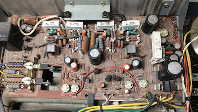
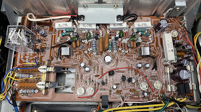
Main amplifier & power supply board - before and after
Phono Amplifier Board (P400)
It is very easy to service the phono amplifier board in Marantz 2238B. This board has six low leakage e-caps C401/C402, C407/C408, C415/C416, and four aluminum e-caps C411/C412, C421, C422. I replaced four signal path e-caps C401/C402 and C415/C416 with high-quality film polyester WIMA MKS2 capacitors. The modern WIMA film caps have zero ESR and a very tight spec on capacitance tolerance. The other two low leakage e-caps C407/C408 have a rated capacitance of 22uF and were replaced with modern low leakage Nichicon UKL caps. Pay attention to the rated voltage of electrolytic capacitors. According to the schematic, both e-caps C407 and C408 have a rated voltage of 6.3V. However, the original capacitors installed in these positions have a rated voltage of 16V. I replaced them with Nichicon UKL caps keeping the same rated voltage as the original. The four aluminum e-caps installed on this board were replaced with low impedance Nichicon UPW/UPM caps. This board has no transistors prone to failure or noise. So, no transistors were replaced.
Test results on original capacitors removed from the phono amplifier board:
C401: rated capacitance – 2.2uF, measured – 1.9uF, ESR – 5.2Ω, deviation: -14%
C402: rated capacitance – 2.2uF, measured – 1.9uF, ESR – 7.7Ω, deviation: -14%
C407: rated capacitance – 22uF, measured – 22uF, ESR – 1.56Ω, deviation: 0%
C408: rated capacitance – 22uF, measured – 22uF, ESR – 1.68Ω, deviation: 0%
C411: rated capacitance – 47uF, measured – 55uF, ESR – 0.72Ω, deviation: +17%
C412: rated capacitance – 47uF, measured – 55uF, ESR – 0.76Ω, deviation: +17%
C415: rated capacitance – 2.2uF, measured – 2.2uF, ESR – 3.6Ω, deviation: 0%
C416: rated capacitance – 2.2uF, measured – 2.2uF, ESR – 3.5Ω, deviation: 0%
C421: rated capacitance – 100uF, measured – 101uF, ESR – 0.17Ω, deviation: +1%
C422: rated capacitance – 47uF, measured – 56uF, ESR – 0.84Ω, deviation: +19%
Phono amplifier board - before and after
Filter Capacitors
I tested two main filter capacitors (in-circuit test) with an Atlas ESR70 capacitance meter. Both caps are still within the factory capacitance tolerance and have almost zero ESR, so I didn't change them. In general, filter capacitors rarely fail in vintage gears, and I usually don't replace them unless their ESR is high.
Two filter capacitors were tested with Atlas ESR70 capacitance meter - both are still in spec
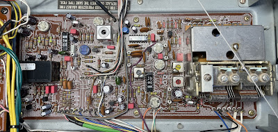
Tuner Board (P200)
Update November 2022: I took this receiver off the shelf and decided to service the tuner board, which was the only board I didn't service initially. I usually don't service the tuner section unless it has an issue. The tuner still works great and has good sensitivity, but I decided to service it anyway as part of preventive maintenance.
Access to the tuner board in Marantz 2238B is excellent and this board is fairly easy to service. This board has seven low leakage e-caps (C172, C219, C304, C305, C319, C320, C322), one bi-polar capacitor (C307), and twenty aluminum electrolytic capacitors (C154, C163, C164, C165, C170, C208, C210, C211, C217, C218, C301,C303, C306, C311, C312, C313, C314, C317, C318, C321). All original low leakage e-caps with the rated capacitance of 1uF were replaced with film polyester WIMA MKS2 caps. The other low leakage e-caps with the rated capacitance of 3.3uF, 4.7uF, and 10uF were replaced with modern low leakage Nichicon UKL caps. The ordinary aluminum e-caps with a rated capacitance of 0.47uF and 1 uF were also replaced with film polyester WIMA MKS2 caps. The original bi-polar e-cap C307 was replaced with a film polyester Kemet capacitor. And the remaining aluminum e-caps were replaced with low impedance Nichicon UPW caps.
Test results of the original capacitors removed from the tuner board showed that 11 out of 28 capacitors have a capacitance tolerance of more than 20%. I checked the tuner alignment after replacing old electrolytic capacitors and it has slightly shifted. I followed the service manual and re-adjusted the high-end tuning and the primary core of discriminator transformer L202. All other alignment points were very close to their optimal positions. So be aware that the tuner alignment might be required after replacing old e-caps on the tuner board.
Test results on original capacitors removed from the tuner board:
C154: rated capacitance – 100uF, measured – 111uF, ESR – 0.52Ω, deviation: 11%
C163: rated capacitance – 1uF, measured – 1.1uF, ESR – 2.8Ω, deviation: 10%
C164: rated capacitance – 10uF, measured – 13uF, ESR – 1.58Ω, deviation: 30%
C165: rated capacitance – 4.7uF, measured – 6.2uF, ESR – 1.73Ω, deviation: +32%
C170: rated capacitance – 100uF, measured – 112uF, ESR – 0.26Ω, deviation: +12%
C172: rated capacitance – 4.7uF, measured – 4.7uF, ESR – 1.75Ω, deviation: 0%
C208: rated capacitance – 4.7uF, measured – 6.4uF, ESR – 1.9Ω, deviation: +36%
C210: rated capacitance – 22uF, measured – 25uF, ESR – 1.45Ω, deviation: +14%
C211: rated capacitance – 0.47uF, measured – 0.59uF, ESR – N/A, deviation: +26%
C217: rated capacitance – 1uF, measured – 1.1uF, ESR – 2.9Ω, deviation: +10%
C218: rated capacitance – 1uF, measured – 1.1uF, ESR – 2.6Ω, deviation: +10%
C219: rated capacitance – 1uF, measured – 1.1uF, ESR – 5.1Ω, deviation: +10%
C301: rated capacitance – 4.7uF, measured – 6.2uF, ESR – 1.47Ω, deviation: +32%
C303: rated capacitance – 100uF, measured – 95uF, ESR – 0.29Ω, deviation: -5%
C304: rated capacitance – 3.3uF, measured – 2.8uF, ESR – 4.3Ω, deviation: -15%
C305: rated capacitance – 1uF, measured – 1uF, ESR – 4.1Ω, deviation: 0%
C306: rated capacitance – 1uF, measured – 1.2uF, ESR – 2.6Ω, deviation: +20%
C307: rated capacitance – 0.22uF, measured – 0.24uF, ESR – N/A, deviation: +9%
C311: rated capacitance – 10uF, measured – 13uF, ESR – 1.58Ω, deviation: +30%
C312: rated capacitance – 10uF, measured – 13uF, ESR – 1.73Ω, deviation: +30%
C313: rated capacitance – 2.2uF, measured – 2.8uF, ESR – 1.67Ω, deviation: +27%
C314: rated capacitance – 2.2uF, measured – 2.7uF, ESR – 1.74Ω, deviation: +23%
C317: rated capacitance – 0.47uF, measured – 0.59uF, ESR – N/A, deviation: +26%
C318: rated capacitance – 0.47uF, measured – 0.59uF, ESR – N/A, deviation: +26%
C319: rated capacitance – 4.7uF, measured – 4.8uF, ESR – 1.72Ω, deviation: +2%
C320: rated capacitance – 4.7uF, measured – 4.7uF, ESR – 1.65Ω, deviation: 0%
C321: rated capacitance – 100uF, measured – 91uF, ESR – 0.42Ω, deviation: -9%
C322: rated capacitance – 10uF, measured – 9uF, ESR – 5.4Ω, deviation: -10%
The two NPN transistors installed at positions Q303 and Q304 are 2SC1344. This transistor does not age well and can create static or result in open circuit faults. I replaced them with low noise Fairchild KSC1845 transistors. Watch the pinout on replacement transistors. The original transistor is BCE and the new one is ECB.
Tuner board - before and after
Power Transistors
Update November 2022: I also decided to replace all original power transistors in this unit. The original transistors were removed, degreased, and tested with Atlas DCA55 semiconductor analyzer. The measured DC current gain on all transistors was in spec according to the datasheet. However, I decided to replace them anyway with new MJ21194/MJ21193 ON Semiconductors transistors as part of preventive maintenance. The old thermal pads were replaced with new Mica ones and a fresh thermal compound was applied.
Power transistors - original Marantz and new ON Semiconductors
Dial and Meter Lamps
The best way to access the dial lamps in Marantz 2238B is by removing the board from the plastic holder. However, this holder usually becomes very brittle due to aging and the small plastic tabs can be easily broken. It is safer to replace old incandescent dial bulbs from the front panel. However, one should remove the faceplate and the dial scale to do it. The dial scale is mounted on the chassis by double-sided tape. It is always a risk to break it if inappropriate tools are used. I usually use an X-ACTO #2 Knife for this job and work very slowly and with patience. The old incandescent dial bulbs were replaced with warm white LED lamps to maintain the original look and decrease heat.
To replace the original incandescent bulbs behind the meters in Marantz 2238B, one should remove a small PCB holding the bulb. The small plastic tab will snap off for sure while trying to do it. But this is the only way to replace these bulbs behind each meter. Sad but true. However, I am always able to glue these small plastic tabs back after bulb replacement. It takes some patience but is doable. I strongly recommend using modern LED lamps (warm white or cool blue) here instead of new incandescent bulbs. The LED lamps not only substantially reduce the heat and thereby protect the vellum paper behind the meters but also will last almost forever. You wouldn't need to replace them and face the same trouble again.
Original incandescent dial bulbs - two out of five bulbs burned out
Power Supply Adjustment
There is an error in the service manual regarding the power supply adjustment. The service manual says to connect the voltmeter between pins J722 and J724 which is incorrect. The voltmeter should be connected between pins J722 (+) and J728 (-). The pin J728 is ground. Then, under no-signal conditions, the voltage between these two pins should be adjusted to +35.0V with the trimming resistor R787.
Bias and DC Offset Adjustments
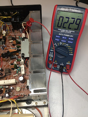
The bias is measured across two emitter resistors (wire wound type, 0.39Ω/3W). The voltage drop across resistors R763 and R765 should be adjusted to ~23mV DC with the trimming resistor R731. This is a bias on the left channel. And on the right channel, the voltage drop across resistors R764 and R766 should be adjusted to ~23mV DC with the trimming resistor R732.
The DC offset is measured between pins J717 and J714 on the left channel and between pins J718 and J714 on the right channel. It should be adjusted as close to zero volts as possible with the trimming resistors R711 and R712, respectively.
Bias on the left and right channels after restoration
DC offset on the left and right channels after restoration
Output Power Test
At the end of my restoration, I loaded this receiver with a low inductance 8Ω/100W dummy resistor for each channel, connected my oscilloscope across the speaker terminals, and applied a sine-wave signal of 1kHz to the AUX jacks. The output sine-wave signal was perfectly symmetrical on both channels with no clipping up to 17.52 VRMS (left channel) and 17.64 VRMS (right channel). So, one can calculate that the output power is (17.52 x 17.52)/8=38.4W (left channel) and (17.64 x 17.64)/8=38.9W (right channel). It even slightly exceeds a factory specification for this model which is not too bad for 43 years old gear!
Output power test - meets and even exceeds a factory specification!
All the knobs and the faceplate were gently cleaned in warm water with dish soap. The final result can be seen in the photos below. The receiver looks brand new again and sounds fantastic! Please watch a short demo video at the end of this post. Thank you for reading.
Marantz 2238B - after restoration











Very nice restoration, Oleg! I am the one who contacted you a few weeks back about a Marantz 2252B. I'll probably be bringing it to you for service. It's amazing how dirty these things get, but I build/service PCs and laptops as a hobby, so I am familiar with fine dust getting into every nook and cranny.
ReplyDeleteVery nice article, thank you!
ReplyDeleteI'm very lucky to find this very helpful article. I'm on my way to recapping also change all suspect noise transistor.
ReplyDeleteThe first board I recapped is P700 and I still wonder is it true that caps C740 (10uf 50volt) located under pcb? I looking it carefully in diagram but there are no explanation, and after I found this article I'm now sure it is correct location.
I also change 2 old filter caps since it is easy to reach when this pcb can be pulled out. The bigger challange as you mention above is to replace caps at PE01 board (this also push me to search in google if it is possible to do recap without open so many parts surrounding), but I will try to open it although I know it is risky because I plan to change all caps below 4.7uf with wima and all transistors also.
I find many hints that very usefull (since you mention there are some print mistaken and some uncorrect explantion especially point to adjust 35VDC, I think I was made a mistake to follow 2238B service manual. Your article really do enlightment for me. So I think you deserve my huge gratitude and hope you don't mind if I contact you for further discussion. Thank you once again and Happy New Year 2022.
Hi Elsuhan. There are a lot of errors in Marantz service manuals. I have the original (factory issued) service manual for 2238B and the e-cap C740 (10uF/50V) is also missing on the PCB diagram. Take your time and work slowly on your 2238B. And you won't be disappointed with a final result. It is a sweet receiver and sounds great. Happy New Year!
DeleteI sent Oleg my 2238B in March 2022. I am the original owner. I had shelved it for quite some time as my attempts to clean the scratchy volume and balance knobs with tuner cleaner & lubricant became less and less successful over the years. (Oleg can attest to the overspray!)
ReplyDeleteHe serviced the receiver in a very reasonable amount of time and I had it back in Michigan just two days after I sent him payment.
I couldn't be happier with the results! I am thrilled to be able to listen to the sound of my old friend again, just as when I purchased it at the tender age of 13.
Thank you Oleg!!!
Great work you did here! Did you have to replace the Stereo bulb? if so how did you do it? Any ideas how? I tried from above, but it is coming up, and I don't want to force it much. Thanks in advance.
ReplyDeleteGreat job you have done with this receiver. Have you tried replacing the stereo bulb? I have tried from above, but no luck and I am concerned on forcing things too much. Any ideas? Thanks in advance.
ReplyDeleteYes, I have replaced the stereo indicator lamp in this unit. I pulled it out from above. As far as I remember, I loosened the dial indicator guide and moved it to the left to make room. I then used the X-ACTO Knife #2 to pull the bulb out of the rubber socket. You must be careful at this stage. An old socket is usually very fragile and easily damaged. Just take your time and work slowly. Good luck.
Delete