Unit: AM/FM Stereo Receiver
Manufacturer: Fisher
Model: 202
SN: 22247
Another Fisher receiver (Futura series, model 202) came in for restoration. I restored exactly the same model a few months ago and one can read the restoration process in detail here: Fisher 202 receiver restoration. So, this post will be shorter than usual but I want to document what was done on this unit for future references. I hope it will be a good addition to my previous post about the Fisher 202 restoration.
Before I powered up this little receiver I checked the fuses on the back side to make sure that all of them have a correct rated current. There are three fuses on the back side: the main 2A slow blow fuse to protect the unit and two 2.5A slow blow fuses to protect the left and right channels. The fuse protecting the left channel was blown but someone bypassed it with a small piece of aluminum foil (!). Well, I was not surprised since you never know what can be found in these old units... Anyway, I replaced the blown fuse with a new one and powered the receiver up using my Dim Bulb Tester (DBT). The light bulb flashed for a second on bright and then dimmed out almost completely. So, this unit has no short circuit.
Blown fuse - bypassed with a small piece of aluminum foil
Power Amplifier Board
The Fisher 202 has two driver boards. These boards are very easy to service once removed from the slot. I didn't find any signs of overheating on these boards. All transistors and diodes have been tested and no bad components were found. So, I replaced only electrolytic capacitors. The original e-cap C01 installed in the signal path has a relatively high equivalent series resistance (ESR) of 2.6Ω (left channel) and 2.2Ω (right channel). I replaced it with a low leakage Nichicon UKL cap. The ESR of a new e-cap is only 1.5Ω which is lower in comparison to the original one. The lower ESR is always better, especially for e-caps installed in the signal path. The remaining three e-caps C02, C03, and C04 were replaced with low impedance and high-reliability Nichicon UPW capacitors. All original e-caps removed from the power amplifier board were tested with Atlas ESR70 capacitance meter and the results are below.
Test results on original capacitors removed from the power amplifier board:
C01-L: rated capacitance – 1uF, measured – 1.44uF, ESR – 2.6Ω, deviation: +44%
C01-R: rated capacitance – 1uF, measured – 1.36uF, ESR – 2.2Ω, deviation: +36%
C02-L: rated capacitance – 100uF, measured – 131uF, ESR – 0.05Ω, deviation: +31%
C02-R: rated capacitance – 100uF, measured – 131uF, ESR – 0.06Ω, deviation: +31%
C03-L: rated capacitance – 220uF, measured – 266uF, ESR – 0.15Ω, deviation: +21%
C03-R: rated capacitance – 220uF, measured – 270uF, ESR – 0.15Ω, deviation: +23%
C04-L: rated capacitance – 47uF, measured – 85uF, ESR – 0.19Ω, deviation: +81%
C04-R: rated capacitance – 47uF, measured – 77uF, ESR – 0.22Ω, deviation: +64%
Left and right driver boards - after servicing
Power Transistors
The original Hitachi power transistors 2SC1030 were removed, cleaned, and tested with Atlas DCA55 semiconductor analyzer. According to the datasheet, the DC current gain measured in each transistor was in spec. However, it should be noted that Atlas DCA55 semiconductor analyzer provides the accurate reading for DC current gain only on low-power transistors. A high-power transistor requires a much higher collector current and collector-emitter voltage to accurately measure its current gain. However, it is still a very useful device for comparing transistors of a similar type for the purposes of gain matching or fault-finding.
I replaced the old thermal pads with new Mica ones and refreshed the thermal compound.
Original power transistors with new pads and thermal compound
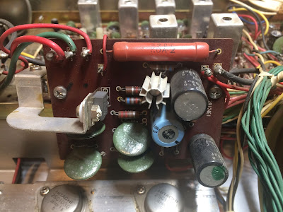
Power Supply Board
The power supply board has three electrolytic capacitors C01, C02, and C03. These were replaced with low impedance Nichicon UPW caps. The new e-caps have a maximum operating temperature of +105C which is a beneficiary in power supply circuits. The original e-caps installed in vintage gears from the 70's have a maximum operating temperature of +85C. All original e-caps removed from the power supply board were tested and the results are below. The ESR of the original e-cap C03 is elevated. The new e-cap installed instead of C03 has a lower ESR of 0.15Ω.
Test results on original capacitors removed from the power supply board:
C01: rated capacitance – 100uF, measured – 134uF, ESR – 0.09Ω, deviation: +34%
C02: rated capacitance – 100uF, measured – 132uF, ESR – 0.07Ω, deviation: +32%
C03: rated capacitance – 220uF, measured – 368uF, ESR – 0.32Ω, deviation: +67%
Power supply board - before and after
Pre-amplifier Board
I replaced all electrolytic capacitors on this board. The e-caps C1 and C2 installed in the signal path were replaced with low leakage Nichicon UKL caps. The original e-cap C1 installed in the right channel has a very high ESR in comparison to C2 in the left channel. The ESR of the Nichicon UKL capacitor is about 1.80Ω. The low ESR is critical for e-caps installed in the signal path. The remaining e-caps were replaced with low impedance Nichicon UPW/UPM caps.
Test results on original capacitors removed from Pre-amplifier board:
C1: rated capacitance – 10uF, measured – 12uF, ESR – 11.6Ω, deviation: +20%
C2: rated capacitance – 10uF, measured – 15uF, ESR – 1.84Ω, deviation: +50%
C9: rated capacitance – 100uF, measured – 152uF, ESR – 0.50Ω, deviation: +52%
C10: rated capacitance – 100uF, measured – 148uF, ESR – 0.46Ω, deviation: +48%
C16: rated capacitance – 100uF, measured – 154uF, ESR – 0.04Ω, deviation: +54%
Pre-amplifier board - before and after
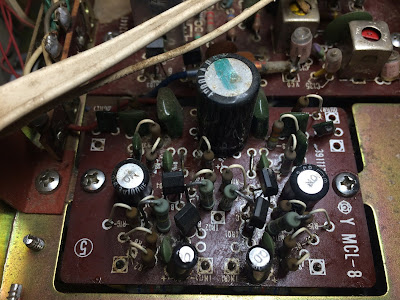
Control Amplifier Board
All electrolytic capacitors on this board are installed in the signal path. The exception is only the e-cap C525. I replaced e-caps C503/C504, C511 thru C514, and C517/C518 with low leakage Nichicon UKL caps. The e-cap C525 was replaced with a low impedance Nichicon UPW cap.
This board also has four noisy 2SC458LG transistors and I replaced them with modern low noise Fairchild KSC1845. The new transistors were carefully matched by current gain and base-emitter voltage within 1%. Watch the pinout on replacement transistors. The original transistor is BCE and the new one is ECB.
I tested all original 2SC458LG transistors from this board with Atlas DCA55 semiconductor analyzer. One transistor TR501 from the left channel was found leaky. The measured collector leakage current was 0.026mA which is substantial for Si transistor. A leakage current is expected to be less than 0.001mA for the Si transistor.
Test results on original capacitors removed from Control amplifier board:
C503: rated capacitance – 10uF, measured – 19uF, ESR – 2.5Ω, deviation: +90%
C504: rated capacitance – 10uF, measured – 17uF, ESR – 2.6Ω, deviation: +70%
C511: rated capacitance – 4.7uF, measured – 6.9uF, ESR – 2.2Ω, deviation: +47%
C512: rated capacitance – 4.7uF, measured – 6.9uF, ESR – 2.2Ω, deviation: +47%
C513: rated capacitance – 1uF, measured – 1.7uF, ESR – 2.7Ω, deviation: +70%
C514: rated capacitance – 1uF, measured – 1.3uF, ESR – 2.2Ω, deviation: +30%
C517: rated capacitance – 1uF, measured – 1.2uF, ESR – 3.0Ω, deviation: +20%
C518: rated capacitance – 1uF, measured – 1.3uF, ESR – 2.2Ω, deviation: +30%
C525: rated capacitance – 220uF, measured – 268uF, ESR – 0.04Ω, deviation: +22%
Faulty transistor TR501 from the left channel - substantial leakage current
Control amplifier board - before and after
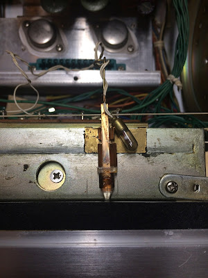
Dial, Dial Pointer, and Stereo Indicator Lamps
The dial pointer and two stereo indicator bulbs burned out in this unit. I replaced them with new white LED lamps. The new LED lamps will virtually last forever. I also replaced the original incandescent bulbs with cool blue LED lamps to decrease heat and improve the illumination. I found that the cool blue LED lamp makes the illumination of the dial scale more uniform in this model.
Burned original dial pointer bulb
Burned original stereo indicator bulbs
New white LED lamps installed
New cool blue LED lamps installed
Center Voltage Adjustment
The center voltage adjustment is a straightforward procedure and is clearly described in the service manual. The DC voltage between pin 5 of the left/right channel driver board and the ground should be adjusted to ~31V. I adjusted the center voltage at pin 5 to ~30.7V on each channel since the voltage measured at pin 3 was 61.4V. In general, the DC voltage at pin 5 should always be half of the voltage at pin 3.
Center voltage adjustment - left channel
Center voltage adjustment - right channel
Voltage measured between pin 3 and the ground
All the knobs and the faceplate were gently cleaned in warm water with dish soap. Also, all pots and switches have been cleaned with DeoxIT 5% contact cleaner and lubricated with DeoxIT FaderLube 5% spray.


Hi, I didn't realize this was copyright protected. I have same receiver I bought after Vietnam and tried to put it back in service and one channel is out. Respectfully, David Michael
ReplyDeleteHello David, no problem. I sent you an email with a service manual for Fisher 202. Good luck with restoration!
DeleteExcellent restoration! and well detailed in the photos.
ReplyDeleteI have the lower wattage version of this one, The 201
But i need to replace the signal/stereo lamps due to being out.
Hello Rob, replacing two signal and two stereo indicator lamps in this model is a pretty easy task. Please refer to my other post regarding Fisher 202 restoration (SN: 15547, published on November 18, 2020, link below). Two stereo indicator lamps have red wires and are held in the rubber lamp holder. Two signal strength lamps have white wires and are mounted on the chassis behind the meter.
Deletehttps://www.olegvintageaudio.com/2020/11/fisher-202-receiver-restoration.html
Hi there!
ReplyDeleteCould you please tell me type of the led lamp that you put into the dial pointer?
Hello, the original dial pointer lamp has a diameter of 4.7mm. The diameter of the new LED lamp is ~4 mm. Thus, it may loosen a little in the holder. But this can be fixed with additional heat shrink. I bought these warm white LED bulbs from Parts Express a few years ago. I don't remember if it has any particular type or serial number.
DeleteCan you tell me if you can replace the 2SA537A and 2SC7808A transistors on the power board with what is the best equivalent? Is it wrong in the SM's electrical diagram between 2SA565 and 2SA537?
ReplyDeleteHello, I would use KSA1220 to replace the original 2SA537 transistor and KSC2690 to replace the original 2SC708.
DeleteThank you so much!
Deletehi i have the same amp but the aux is not working do you have a manual or schematic for me ,my 202 has a wooden case /thanks
ReplyDeleteYes, I have a service manual. Please email me at repair@olegvintageaudio.com
DeleteGreat work, I just dusted off the fisher 202 to give to my brother inlaw. Deoxed the volume control. Sounds good . I like how those 2 boards come out as a pair. What I can't figure out is how to get to the tuner lights. Any help would be appreciated.
ReplyDeleteJon
Jon, are talking about dial lamps? Just unscrew the two small screws at the top of the dial and the plate holding all the dial lights will come free.
DeleteExcellent work. Sure do wish I had a service center for all my vintage gear close by. Seems no one works on audio equipment anymore. Sad
ReplyDeletehaving a hard time finding a manual/schematics for this one.
ReplyDeleteI have a service manual. Please email me at repair@olegvintageaudio.com
Delete