Unit: AM/FM Stereo Receiver
Manufacturer: Fisher
Model: 202
SN: 15547
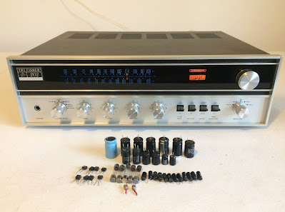
Today I am showing a little Fisher 202 receiver that came in for restoration. The Fisher 202 was introduced in 1970 and was the first of the Futura series. It produces 28 watts per channel into 8 ohms with 0.5% total harmonic distortion. The receiver has one phono input, one tape input, and two Aux inputs. The list price in 1970 was $249.95. The optional walnut veneer cabinet for this model is 21-UW.
The previous owner told me that the right channel in this receiver is dead. I checked three fuses on the back side and found that one fuse protecting the right channel is blown. I replaced the blown fuse and powered up this little receiver using my Dim Bulb Tester (DBT) to check that there are no short circuits. For more information on Dim Bulb Tester refer to my previous post on Craig 5502 restoration. The receiver passed the test with DBT and I removed the cover to look inside.
Power Amplifier Board
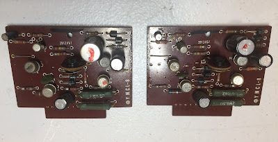
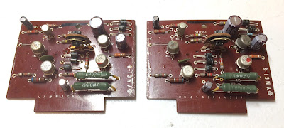
The power amplifier in Fisher 202 is very easy to service since each channel has a separate driver board inserted in the slot. I removed both boards for inspection and immediately realized that the resistor R10 on the right channel board is severely overheated. I measured its resistance and it was 267Ω. The same resistor on the left board was 183Ω. The schematic says the resistor R10 is supposed to be 180Ω. The overheated resistor from the right channel is definitely not original. I unsoldered the resistor R10 from both boards and replaced it with a new metal film resistor 180Ω/0.5W. I also tested all other electronic components (transistors, diodes, and remaining resistors) on each driver board. No other problems with electronic components were found on those boards. I replaced the electrolytic capacitor C01 with a low leakage Nichicon UKL cap. The remaining three e-caps C02, C03, and C04 were replaced with low impedance and high-reliability Nichicon UPW capacitors.
Test results on original capacitors removed from Power Amplifier board:
C01-L: rated capacitance – 1uF, measured – 1.7uF, deviation: +70%
C01-R: rated capacitance – 1uF, measured – 1.8uF, deviation: +80%
C02-L: rated capacitance – 100uF, measured – 124uF, deviation: +24%
C02-R: rated capacitance – 100uF, measured – 165uF, deviation: +65%
C03-L: rated capacitance – 220uF, measured – 261uF, deviation: +19%
C03-R: rated capacitance – 220uF, measured – 275uF, deviation: +25%
C04-L: rated capacitance – 47uF, measured – 68uF, deviation: +45%
C04-R: rated capacitance – 47uF, measured – 66uF, deviation: +40%
Left and right driver boards - before servicing
Overheated resistor R10 on the right driver board
Resistor R10 installed on left driver board
Driver boards - after servicing
Driver boards installed
Power Transistors
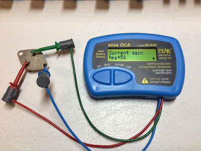
The original Hitachi power transistors 2SC1030 were removed, cleaned, and tested with Atlas DCA55 semiconductor analyzer. The DC current gain was in spec according to the datasheet. Each pair was also very well matched within ~3%. It should be noted that Atlas DCA55 semiconductor analyzer provides the accurate reading for DC current gain only on low power transistors. A high-power transistor requires a much higher collector current and collector-emitter voltage to accurately measure its current gain. However, it is still a very useful device for comparing transistors of a similar type for the purposes of gain matching or fault-finding.
I applied a fresh thermal compound and also replaced the old thermal pads with new Mica ones.
Power transistors tested with Atlas DCA55 semiconductor analyzer
Old thermal pad - the thermal grease is almost completely dried out
Original power transistors with new pads and fresh thermal compound
Power Supply Board
The power supply board provides +15.5V DC for the tuner, +31.5V DC for the pre-amplifier and control amplifier, and +62V DC for a power amplifier. This board has 3 electrolytic capacitors C01, C02, and C03. I replaced all e-caps with low impedance and high-reliability Nichicon UPW/UPM caps. The test results on the original e-caps removed from this board are below. All of them are outside of the factory capacitance tolerance +/- 20%.
Test results on original capacitors removed from the power supply board:
C01: rated capacitance – 100uF, measured capacitance – 161uF, deviation: +61%
C02: rated capacitance – 100uF, measured capacitance – 142uF, deviation: +42%
C03: rated capacitance – 220uF, measured capacitance – 287uF, deviation: +31%
Power Supply board - before and after
Pre-amplifier Board
The pre-amplifier board has 5 electrolytic capacitors: C1/C2, C9/C10, and C16. Two signal path capacitors C1 and C2 were replaced with low leakage Nichicon UKL caps. The remaining e-caps were replaced with low impedance and high-reliability Nichicon UPW/UPM caps. Four NPN transistors 2SC458LG installed on this board are prone to create noise or work improperly. I replaced those transistors (TR01 thru TR04) with modern low-noise Fairchild KSC1845. The new transistors were gain matched within 1%. Watch the pinout on replacement transistors if you need to service this board. The original transistor is BCE and the new one is ECB. The original electrolytic capacitors and transistors removed from the pre-amplifier board were tested to check their long-term reliability. As expected all e-caps are outside of the factory capacitance tolerance +/- 20%.
Test results on original capacitors removed from the pre-amplifier board:
C1: rated capacitance – 10uF, measured – 19uF, deviation: +90%
C2: rated capacitance – 10uF, measured – 13uF, deviation: +30%
C9: rated capacitance – 100uF, measured – 158uF, deviation: +58%
C10: rated capacitance – 100uF, measured – 160uF, deviation: +60%
C16: rated capacitance – 100uF, measured – 158uF, deviation: +58%
Pre-amplifier board - before and after
Pre-amplifier board - all new Fairchild KSC1845 transistors are gain matched
Control Amplifier Board
The control amplifier board has nine aluminum electrolytic capacitors: C503, C504, C511, C512, C513, C514, C517, C518, and C525. All capacitors except the filtering cap C525 were replaced with low-leakage Nichicon UKL caps. The e-cap C525 was replaced with a low-impedance and high-reliability Nichicon UPW cap. Four noisy 2SC458LG transistors were replaced with modern low-noise Fairchild KSC1845. The new transistors were gain matched within 1%.
Test results on original capacitors removed from the control amplifier board:
C503: rated capacitance – 10uF, measured – 19uF, deviation: +90%
C504: rated capacitance – 10uF, measured – 18uF, deviation: +80%
C511: rated capacitance – 4.7uF, measured – 6.1uF, deviation: +30%
C512: rated capacitance – 4.7uF, measured – 6.0uF, deviation: +28%
C513: rated capacitance – 1uF, measured – 1.6uF, deviation: +60%
C514: rated capacitance – 1uF, measured – 1.6uF, deviation: +60%
C517: rated capacitance – 1uF, measured – 1.6uF, deviation: +60%
C518: rated capacitance – 1uF, measured – 1.6uF, deviation: +60%
C525: rated capacitance – 220uF, measured – 282uF, deviation: +28%
Control amplifier board - before and after
Dial and Stereo Indicator Lamps
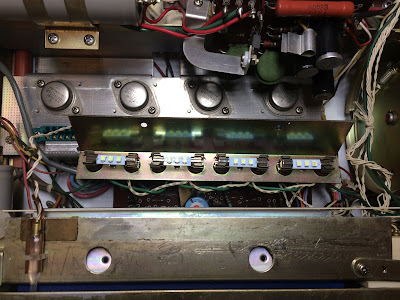
It is very easy to replace the old dial bulbs in Fisher 202. Just unscrew two small screws on the top of the dial plate and the plate holding all dial lamps would be released. I replaced the original incandescent bulbs with warm white LED lamps to maintain the original look and decrease heat.
Two stereo indicator bulbs burned out. I replaced them with new white LED lamps.
Old incandescent dial bulbs
New warm white LED lamps installed
Old stereo indicator bulbs
New white LED lamps installed
Center Voltage Adjustment
The center voltage adjustment is a straightforward procedure. The multimeter should be connected between pin 5 of the left/right channel driver board and the ground. With no signal input, the DC voltage at pin 5 should be adjusted to 31V. In general, the DC voltage at pin 5 should always be half of the voltage at pin 3. So, I adjusted the center voltage at pin 5 to ~31.5V on each channel since the voltage measured at pin 3 was 63V.
Center voltage adjustment - left channel
Center voltage adjustment - right channel
As a routine procedure on all vintage gears I restore, all the knobs and the faceplate were gently cleaned in warm water with dish soap. Also, all pots and switches have been cleaned with DeoxIT 5% contact cleaner and lubricated with DeoxIT FaderLube 5% spray.











Very impressive description.
ReplyDeleteThank you Steve!
DeleteGreat work on this lovely receiver, and great overview of the work done. I look forward to future posts.
ReplyDeleteThank you toymanmsp! I am going to post my restoration work on Pioneer SX-780 today or tomorrow.
DeleteI bought one new in 1971. Kept it for 18 years and traded it for a guitar. Good thing it can't talk!
ReplyDeleteA lot of interesting activity happened in front of that unit by candle light!
Thanks for posting these! Really appreciate it.
ReplyDeleteI also love seeing your work Oleg!!! very enjoyable to follow.
ReplyDeleteThank you!
DeleteJust stumbled across this thread, and wow this is some great information! Very nice restoration work as well! Big thanks for sharing the process!
ReplyDelete